Analog filter realization
Realize an analog filter on a microcontroller
Introduction
Analog filters are used to remove parts of the frequency range from a continuous-time signal. The output of the filter is also a continuous-time signal.
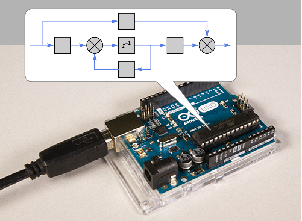
In order to realize an analog filter using a microcontroller the filter needs to be discretized. This is because a microcontroller is a digital device. The analog input to the microcontroller is also discretized. The filter output can be sent to a PWM channel or any other bus available on the microcontroller.

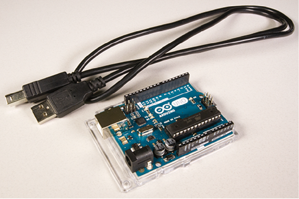
In this project, we will discretize a Butterworth filter and deploy it to an Arduino Uno microcontroller board. The microcontroller will also be configured to receive and send data over the serial bus. We will then use the device framework to send a noisy signal and receive the filtered signal back.
Discretize and deploy the filter
A third-order Butterworth filter with a cutoff frequency 2 Hz.
Discretize the model with sampling period 0.4 seconds.
Load the package.
Embed the model and set it up to receive and send data using the serial connection.
Send and receive data
Open a serial connection to the device.
Specify the input signal and initialize the starting time and filtered signal list.
Set up a task to send and receive data.
Plot the filtered signal.
Remove the task and close the device after some time.
Compare the signals
Compare the input signal and the filtered real-time signal.
Simulate the response of the filter.
Compare the filtered signals.
We see that the sampling period is good enough for the performance of the discretized filter to be on par with the simulated filter.
More things to try
- What happens if you increase or decrease the sampling period?
- How easy is it to replicate this on another microcontroller?
- What if the input signal is an analog signal, or if it’s coming over the I2C bus?
- What are the other ways the output signal can be sent out?
Related Functions
MicrocontrollerEmbedCode . ButterworthFilterModel . ToDiscreteTimeModel . Serial
