Deploy code to a microcontroller to control the speed of a DC motor
Introduction
A DC motor is easy to control. The one that is going to be used in this project is controlled by the input voltage. The higher the voltage, the higher the speed.
However the situation becomes a bit knotty when the motor has to deal with varying loads. The voltage needs to be adjusted on the fly to maintain the desired speed. Thus we need a controller that measures the actual speed, compares it to the desired speed, and inputs the appropriate voltage to the motor.
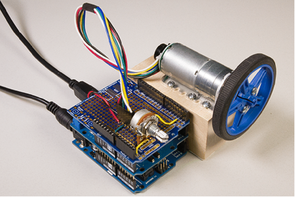
In this project, we will deploy a speed controller to an Arduino microcontroller. The actual speed of the motor is measured using an encoder. The desired speed is set using a potentiometer. The motor is powered using a motor shield. Finally, the reference and actual speeds are transmitted over a serial RS-232 bus that will be read using the device framework.
The project will first demonstrate how to obtain the model of the DC motor and design a controller. Following this we will demonstrate how to read the digital encoder signal and the analog potentiometer signal, and how to output the serial data and the analog PWM motor signal that maintains the desired speed.
The controller also changes the way we interact with the system. Without the controller, we interact with the system directly using the voltage. With the controller, we specify the desired speed to the controller and let the controller figure out the rest.
Parts

Pololu 9.7:1 Metal Gearmotor 25Dx48L mm LP 6V with 48 CPR Encoder [link]
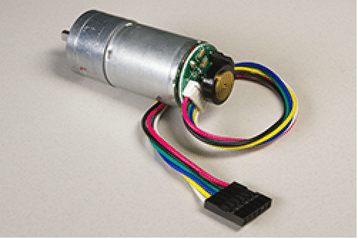
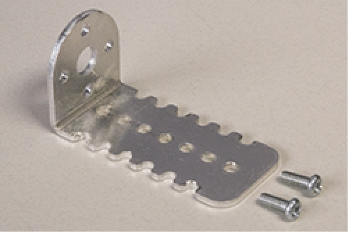
Pololu 25D mm Metal Gearmotor Bracket [link]
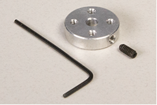
Pololu Universal Aluminum Mounting Hub for 4mm Shaft #4-40 Holes [link]
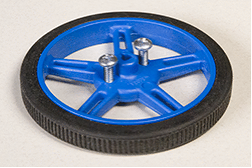
Pololu Wheel 60×8mm [link] and 2 #4-40 1/2" machine screws [link]
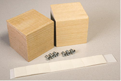
2 wooden square blocks [link], 4-6 #4-40 1/4" Machine screws [link], and adhesive mounting squares [link]
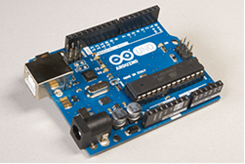
Arduino Uno [link]
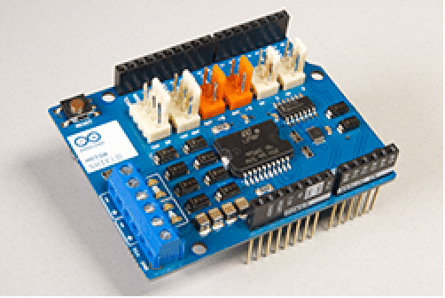
Arduino motor shield [link]
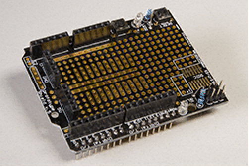
Protoshield [link]
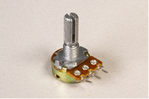
Potentiometer [link]
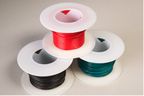
Misc electric wires [link]
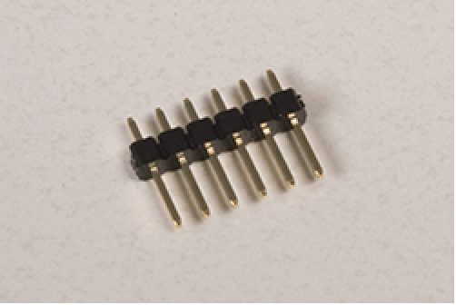
6-pin male header [link]
USB cable [link]
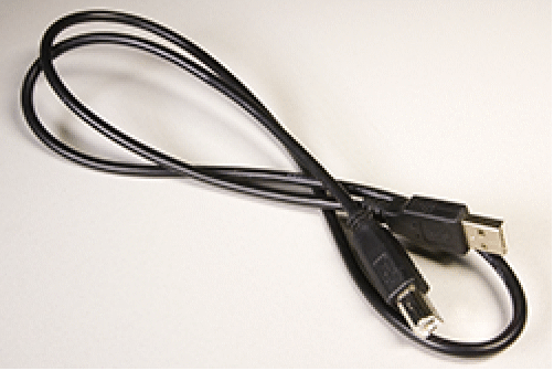
Power supply adapter [link]
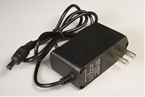
A solderless breadboard [link] and male-to-male jumper wires [link] can be used in lieu of the protoshield, wires, and header.
Assembly
Glue together two square blocks, attach 4 adhesive squares to the base of the block at the 4 corners to prevent vibrations, and mount the bracket onto the square blocks using the 1/4” screws:
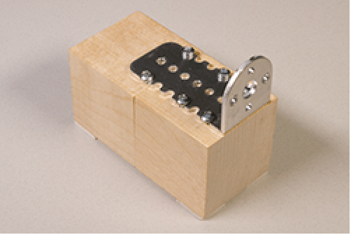
Mount the motor on the Gearmotor bracket using two M3 screws that come with the bracket:
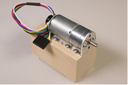
Mount the mounting hub on the motor shaft using the set screw and Allen wrench that come with the mounting hub:
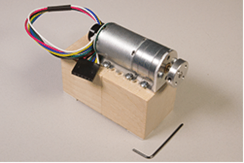
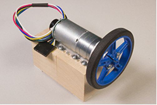
Mount the wheel on the mounting hub using two 1/2” screws:
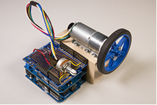
Wire the connections between the motor shield, motor header and potentiometer (this can be done using a protoshield or using a breadboard):
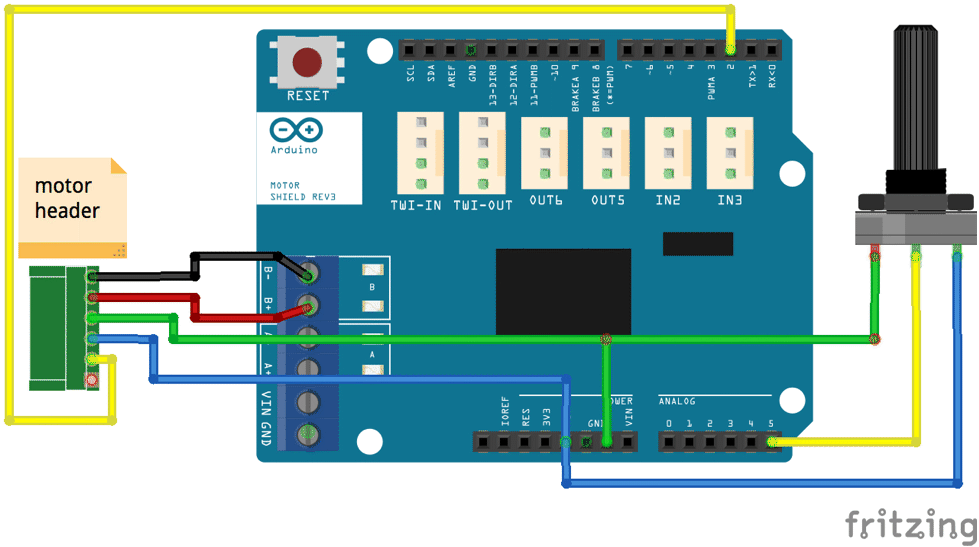
(The colors of the wires from the motor header match with the colors in the schematic.)
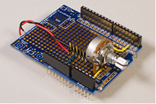
Stack the the motor shield and protoshield on top of the Arduino board:
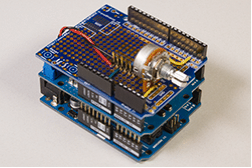
Connect the stacked boards to the motor using the header:
Model of the DC motor
The input-output model of a DC motor with voltage as input and speed as output is a first-order system. The two parameters of a first-order system are the gain and the time-constant. We will now send and acquire some data form the motor to determine these parameters.
The sampling period is not overly critical because it is just acquiring data.
The motor has a gear ratio of 9.68:1 and the motor's encoder gives 12 counts per revolution. Convert it to get the rotations per minute (rpm) of the output shaft.
We will create a model that accepts the duty cycle as input and sends it to the motor. It will also read the encoder signal and trasmit it.
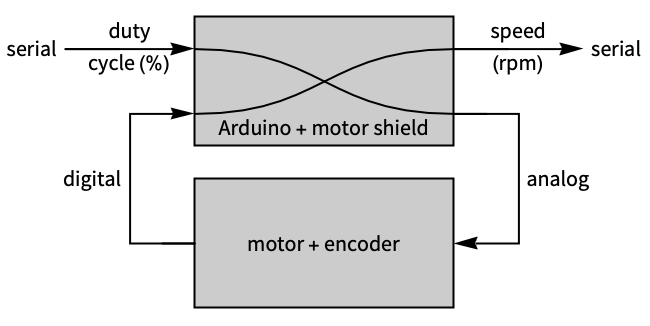
The duty cycle input is sent over serial and the speed is obtained using the rising edges of the encoder.
The model’s outputs are the duty cycle and the speed of the motor which is sent over serial.
The model transmits the serial duty cycle signal as a PWM signal. The second input which is the rising edge counts of the encoder is converted to rpm and sent back over the serial.
After embeding the model, the Arduino will read the serial duty cycle value and send back the resulting motor speed.
Open a connection to the microcontroller.
A function that converts the incoming characters to an expression.
Start a scheduled task that receives the speed and sends the duty cycle.
Create two gauges to set the duty cycle and read the motor speed.
Set the duty cycle and wait for the speed to stabilize before recording it. Also for each duty cycle, measure the actual voltage that was applied to the motor. This is the voltage across the terminals B of the motor shield.
Stop the task and close the connection to the microcontroller.
Plot the measured voltage vs speed.
Except for one erratic data point, we see that the plot is linear.
We will neglect the offset and set the gain of the motor as the slope of the plot.
To determine the time constant of the motor we will look at its response to a step input. For this, open the connecton to the Arduino and restart the scheduled task. Abruptly increase the duty cycle and wait for the speed to stabilize. Then close the connection and stop the scheduled task.
Plot the speed response of the motor and zoom in on the portion where it starts from the initial speed and stabilizes at the final speed.
We see that the motor takes 5 seconds to reach the steady-state value. From the fact that the settling time is roughly 4 time-constants, we can estimate the time-constant.
The model of the motor withe voltage as input and speed as the output.
Model of the motor shield
While the actual input to the motor and the model is the voltage, the Arduino does not send a voltage signal out. It sends the duty cycle. The actual voltage is applied by the motor shield. Thus we need to figure out the conversion from the voltage to the duty cycle, which is then sent out as a voltage by the motor shield.
The plot of the voltage vs duty cycle.
We will approximate this using a piecewise function.
A function to fit the data.
The fit.
The measured and fitted data.
The model of the inverse of the power electronics on the shield. The sampling period to be used by the controller will be determined later.
Controller design and deployment
Design a PID controller with sampling period 0.25 seconds.
The model that gets the encoder readings in rpm.
The reference is set by a potentiometer with range 0V to 5V. Rescale it to read 0 to 500 rpm.
The comparator to compare the reference speed and the actual encoder speed.
The controller has 2 inputs and 3 outputs.
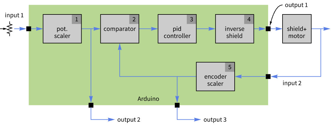
The first input is the reference speed that is set by the potentiometer value. The second input is the actual speed that is measured by the encoder.
The first output is the duty cycle of the PWM signal that drives the motor. The other two are the reference and actual speed transmitted over a serial RS-232 connection.
The complete controller.
Load the package.
Deploy the code.
Testing
Open a serial connection to the target.
Create a function to parse the actual and reference speed values coming though the serial connection.
Set up a scheduled task to read the values every 0.25 seconds.
Plot the results showing the response to set reference values and disturbances.
Terminate the scheduled task and device connection.
We observe that the controller performs reasonably well.
More things to try
- Implement an open-loop controller and compare the differences.
- Try other closed-loop control designs.
- Control the speed in both the clockwise and counterclockwise directions.
- Increase or decrease the sampling period and see its effect on the performance.
- See how much the serial communication contributes to the code size.