Deploy code to the Zumo robot so it follows a path
Introduction
The Zumo robot by Pololu is a tracked robot which is driven by two motors and has an array of IR sensors which can be used for path following.
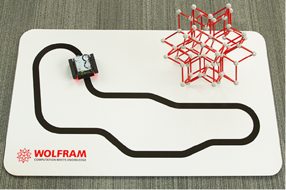
In this project, we will develop a path following controller, integrate it with libraries provided by Pololu to interface with the sensors and motors, and deploy them to the microcontroller that will enable the robot to do path tracking.
Parts

Zumo Robot for Arduino, v1.2 [link]

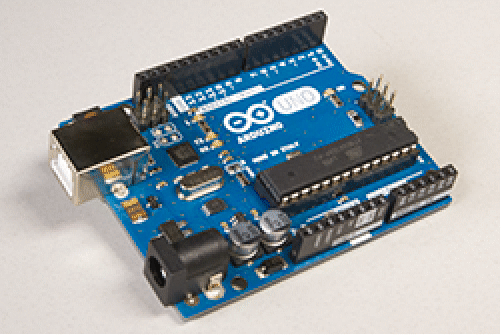
Arduino Uno [link]
4 Rechargeable NiMH AA batteries [link]

USB cable [link]
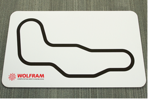
Track to test the robot
Protractor [link]

The assembly is straightforward. The Zumo robot is essentially a shield and the Arduino Uno should be stacked upside down on it. The bulldozer-style blade in the front of the robot can be removed or left as is. And do not forget to install the batteries in the housing on the underside of the robot.
Arduino and Zumo libraries
We will be using libraries that have been provided by Pololu. We will also be using an Arduino sketch in the library to figure out the sensor calibration.
If you do not already have them, install the Arduino IDE and also the libraries QTRSensors, ZumoReflectanceSensorArray, Pushbutton, and ZumoMotors. The instructions to install libraries can be found on the Arduino site.
The following is the location of Arduino’s SketchBook directory on a Mac.
If things went successfully, you should have the 4 libraries there.
Model
The inputs to the system are the speeds ![]() and
and ![]() of the left and right motors. This affects the position (x, y) and the orientation θ of the robot.
of the left and right motors. This affects the position (x, y) and the orientation θ of the robot.
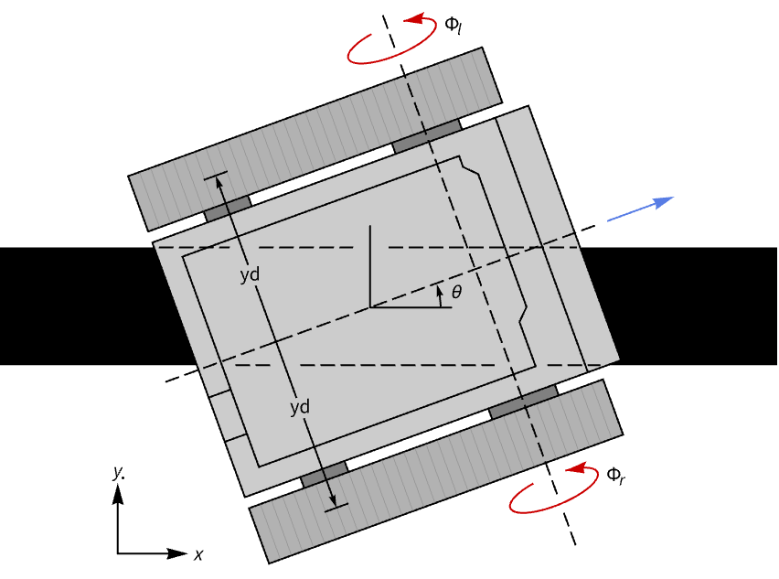
Since we are interested primarily in the orientation of the robot, we will use a simple kinematic model that relates the orientation θ to the motor speeds ![]() and
and ![]() .
.
While the left and right motor speeds are the physical inputs to the system, for purposes of the control design we will consider the inputs as the base base speed Φ and the differential speed Δ.
With the new set of inputs, we clearly see that only the differential speed Δ influences the orientation of the robot. We can assemble a StateSpaceModel with Δ as the input and θ as the output.
The above model will be used to design the controller that orients the robot on the track. The base speed Φ controls the translation motion or speed of the robot and will be designed separately. Thus we see that choosing the new set of inputs helped us to decouple the tracking problem into two separate problems.
Differential input controller design
The angle θ measures the extent to which the robot deviates from the track. To create a robost controller we use both θ and its integral ![]() , and use a model with states
, and use a model with states ![]() and θ for the controller design.
and θ for the controller design.
The model is controllable.
We will design a control law that uses full state fedback.
Because the controller uses full state feedback, i.e it needs the values of both ![]() and θ, and the sensor only measures θ.
and θ, and the sensor only measures θ.
The model is also observable.
Thus we can add an observer to estimate both the states.
The control law and estimator together make up the core controller.
The closed-loop system.
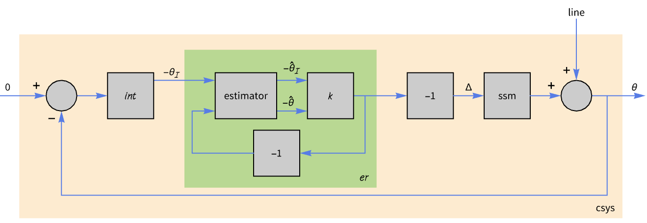
The integrator that was used is not part of the model, but was used only for the controller design. Thus the integrator must be implemented as part of the controller.
The loop gain.
We can verify that the closed-loop system indeed has the poles at the specified locations.
And we can simulate the response of the robot to a differntial input of 15 deg/s.
Also the units of the control input Δ is rad/s, but the library uses units of rpm for the motor speeds. Thus this conversion must also be implemented as part of the controller.
The full core controller.

Finally, discretize the controller so that it can be implemented on the microcontroller.
Speed controller design
We will implement an ad hoc speed controller that slows down the robot when it is making sharp turns and speed it up as the smoothness of the curve gets better.
To prevent the abrupt speed changes seen above, we will also add a moving average filter and integrator to the controller.
Sensor calibration
To carry out the calibration you will need a straight segment of the track and a protractor.
And we will use a sketch already created by Pololu. The sketch is in the ZumoReflectanceSensorArray library that was installed earlier.
Open the sketch and the serial monior from the Arduino IDE, and upload the sketch.
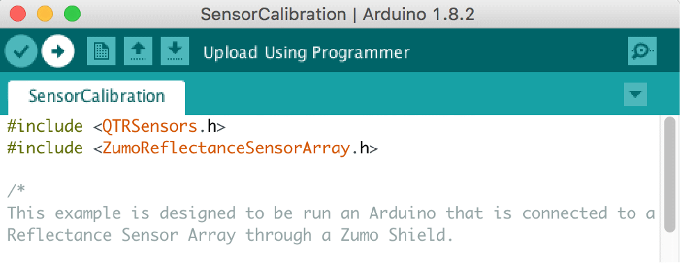
After the sketch is uploaded the LED on the robot will turn on, and will remain on for about 10 seconds. In this period you should gently slide the robot back and forth across the track a couple of times so that the sensor is exposed to both the track and the background.
Following this , orient the robot at various angles relative to the track. Record the sensor readings and the corresponding angles.
Use LinearModeFit to model the relationship between the sensor readings and the orientation of the robot.
Compare the actual and fitted values.
Create an input-output model to get the orientation from the sensor readings.
Complete controller
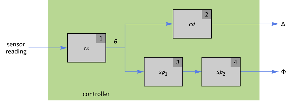
The complete controller comprises of the conversion of the sensor readings, and the differential and speed controllers.
Controller deployment
Before deploying the controller, we need to interface it with the Zumo libraries.

Apart from the sensor and motor libraries we will be using the pushbutton library.
The pushbutton is used to prevent robot moving immediately after the code is downloaded. This gives us time after downloading the code to disconnnect the USB cable and place the robot on the track. Only after the pushbutton is pressed, does the robot start moving.
Use the external libraries to get the sensor readings.
Also use the functionality in an external library to set the actual motor speeds.
The header files to include.
Create the necessary objects.
The initialization code waits for the button to be pressed, initializes the sensors, and self-calibrates them by swiveling the robot around the track so they get a good look at the track and the background.
Load the package.
Embed the controller.
Disconnect the USB cable from the robot, place it on the track, and press the push button.
In conclusion, we have seen how to design a tracking controller and how code from external libraries can be integrated with the auto-generated code.
More things to try
- Change the controller and estimator pole locations and observe how that affects the performance of the controller.
- Design a reduced-order observer instead of a full-order observer.
- Try other contol design techiques.
- Investigate if the speed controller be improved.
- Investigate if the controller is robust enough to handle errors in the sensor calibration.
- Try to design a controller that can also handle crossovers in the track.