Joule Heating of Tungsten Wire
| Introduction | Solve the PDE Model |
| Multiphysics Model | Post-processing and Visualization |
| Domain | Nomenclature |
Introduction
The Joule heating effect, also known as the resistive heating effect, denotes a phenomenon where electric energy is converted into thermal energy as an electric current flows through an object. This effect is commonly found in devices such as electric heaters, incandescent light bulbs and fuses.
In the following model, a voltage of ![]() is applied to a tungsten wire. Heat is then generated within the wire due to the Joule heating effect. Part of the generated heat dissipates from the side surfaces by both thermal convection and radiation to the surrounding air. The remaining heat propagates toward electrode pads at both ends and leaves the wire by thermal conduction. The electrode pads on both ends act like heat sinks and cool the wire down to the ambient temperature
is applied to a tungsten wire. Heat is then generated within the wire due to the Joule heating effect. Part of the generated heat dissipates from the side surfaces by both thermal convection and radiation to the surrounding air. The remaining heat propagates toward electrode pads at both ends and leaves the wire by thermal conduction. The electrode pads on both ends act like heat sinks and cool the wire down to the ambient temperature ![]() .
.
The electric potential field ![]() and the total heat generation
and the total heat generation ![]() are simulated by a stationary current model. Based on these results, the temperature distribution
are simulated by a stationary current model. Based on these results, the temperature distribution ![]() will then be modeled with a heat transfer model. Finally, the amount of heat loss through each surface will calculated and compared.
will then be modeled with a heat transfer model. Finally, the amount of heat loss through each surface will calculated and compared.
The electric potential field ![]() and the total heat generation
and the total heat generation ![]() are simulated by an electrostatic current model. Based on these results, the temperature distribution
are simulated by an electrostatic current model. Based on these results, the temperature distribution ![]() will then be modeled by a heat transfer model. Finally, the amount of heat loss through each surface will calculated and compared.
will then be modeled by a heat transfer model. Finally, the amount of heat loss through each surface will calculated and compared.

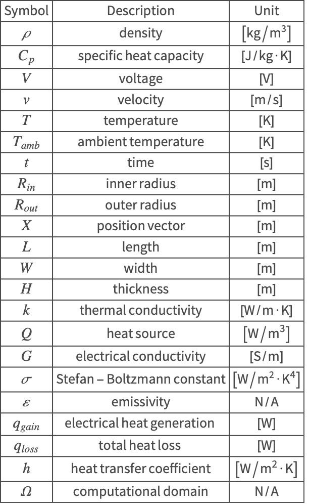
The symbols and corresponding units used here are summarized in the Nomenclature section.
Please refer to the information provided in "Heat Transfer" and "Electric Currents" for a more general theoretical background for heat transfer and electric current analysis, respectively.
Needs["NDSolve`FEM`"]Multiphysics Model
There are two physical domains involved in this application: a stationary current model and a heat transfer model. The coupling between the two models is one-way only, since the temperature field depends on the electric potential but the electric potential field does not depend on the temperature. This type of problem is considered as a sequential multiphysics model and will be solved in two separate steps.
First, the stationary current model model is built to simulate the potential field ![]() in the wire. The heat transfer model is then constructed and uses the potential field previously computed to show the Joule heating effect of the wire.
in the wire. The heat transfer model is then constructed and uses the potential field previously computed to show the Joule heating effect of the wire.
Subscript[ρ, tungsten] = 1.93 * 10^4;
Subscript[Cp, tungsten] = 134;
Subscript[k, tungsten] = 175;
Subscript[G, tungsten] = 1.79 * 10^7;
pars = <|"MassDensity" -> Subscript[ρ, tungsten], "SpecificHeatCapacity" -> Subscript[Cp, tungsten], "ThermalConductivity" -> Subscript[k, tungsten], "ElectricalConductivity" -> Subscript[G, tungsten]|>;
Stationary Current Model
In this model, the electric potential field ![]() is assumed to be independent of the temperature
is assumed to be independent of the temperature ![]() . That is, the electrical conductivity
. That is, the electrical conductivity ![]() is kept at a constant value at all times. The potential field satisfies the stationary current continuity equation:
is kept at a constant value at all times. The potential field satisfies the stationary current continuity equation:
Here, ![]() is the electrical conductivity
is the electrical conductivity ![]() .
.
evars = {V[x, y, z], {x, y, z}};
ElectricCurrentPDEComponent[evars, <|"ElectricalConductivity" -> G|>]
Heat Transfer Model
The heat equation (1) is used to solve for the temperature field in a heat transfer model:
For a steady-state heat transfer model, the transient term in (2) is set to zero. Since a solid is modeled, the internal velocity ![]() also vanishes, and the heat equation simplifies to:
also vanishes, and the heat equation simplifies to:
![]() is the density
is the density ![]() ,
,![]() is the heat capacity
is the heat capacity ![]() ,
,![]() is the thermal conductivity
is the thermal conductivity ![]() .
.
tvars = {T[x, y, z], {x, y, z}};
HeatTransferPDEComponent[tvars, <|"ThermalConductivity" -> k, "HeatSource" -> Q|>]
Domain
The radius of the tungsten wire is ![]() . The simulation domain
. The simulation domain ![]() and the geometric shape of the wire are described in the following plot.
and the geometric shape of the wire are described in the following plot.

L = 0.1;
r = 0.0025;
R = 0.0075;
Next, the 3D domain ![]() is constructed by specifying the path of the tungsten wire.
is constructed by specifying the path of the tungsten wire.
arc1 = Table[R * {Cos[θ], Sin[θ], 0.}, {θ, -π / 2, π / 2, π / 30}];
arc2 = Reverse[-arc1];
arc3 = Table[R * {Cos[θ], Sin[θ], 0.}, {θ, π / 2, 0, -π / 30}];
pathPts = Join[...];Graphics3D[{Thick, Blue, Line[pathPts]}, ...]wire = Graphics3D[{CapForm["Butt"], Tube[pathPts, r]}]Now the boundary mesh region and the full element mesh can be generated. In order to get a good result, a grid finer than the default is used for the mesh generation.
bmeshRegion = DiscretizeGraphics[wire];
mesh = ToElementMesh[bmeshRegion, MaxCellMeasure -> 5 * 10 ^ -10]
In the following sections, the boundary conditions will be set up and the heat flux calculated at both ends and the side surfaces. To do so, the functions leftEndQ and rightEndQ are defined to determine whether a point ![]() is located on the corresponding surface.
is located on the corresponding surface.
tolerance = 0.01r;
leftEndQ[x_, y_, z_] := Abs[x] ≤ tolerance && y^2 + z^2 ≤ r^2
rightEndQ[x_, y_, z_] := Abs[y + r] ≤ tolerance && (x - (L + 2R + r))^2 + z^2 ≤ r^2
A tolerance of ![]() is applied at both ends to account for numerical error in the discretized domain.
is applied at both ends to account for numerical error in the discretized domain.
Solve the PDE Model
In the following section, the stationary current model will be solved first to simulate the potential field ![]() of the wire. The heat transfer model is then constructed to show the heating effect of the electric current.
of the wire. The heat transfer model is then constructed to show the heating effect of the electric current.
Stationary Current Model
There are two types of boundary conditions involved in the stationary current model. At both ends of the wire, an electric potential difference ![]() is applied.
is applied.
Subscript[Γ, volt] =
	{ElectricPotentialCondition[leftEndQ[x, y, z], evars, pars, <|"ElectricPotential" -> 0.2|>], ElectricPotentialCondition[rightEndQ[x, y, z], evars, pars, <|"ElectricPotential" -> 0|>]};
On the remaining boundary, a default electrical insulation boundary condition ![]() is implicitly used.
is implicitly used.
StationaryCurrentModel3D = ElectricCurrentPDEComponent[evars, pars];
pde = {StationaryCurrentModel3D == 0, Subscript[Γ, volt]};Vfun = NDSolveValue[pde, V, {x, y, z}∈mesh];Next, the electric potential field ![]() is visualized within the tungsten wire.
is visualized within the tungsten wire.
VRange = MinMax[Vfun["ValuesOnGrid"]];
legendBar = BarLegend[{"TemperatureMap", VRange}, Rule[...]];
options = {...};Legended[RegionPlot3D[mesh, ColorFunction -> Function[{x, y, z}, ColorData[{"TemperatureMap", VRange}][Vfun[x, y, z]]], Evaluate[options]], legendBar]Since the electric conductivity ![]() is homogeneous throughout the wire, the electric potential decreases linearly from left
is homogeneous throughout the wire, the electric potential decreases linearly from left ![]() to right
to right ![]() .
.
The corresponding heat generated by the electric current can now be calculated from the potential field ![]() . The steady-state temperature field
. The steady-state temperature field ![]() is solved for by the heat transfer model in the following section.
is solved for by the heat transfer model in the following section.
Heat Transfer Model
The electrical heat generation is coupled to the stationary heat equation (3) as the source term ![]() on the right-hand side, which is known as the electromagnetic heat source.
on the right-hand side, which is known as the electromagnetic heat source.
Joule's first law (4) states that the heat generated within an object is equivalent to the product of its conductivity ![]() and the square of the potential gradient.
and the square of the potential gradient.
Q = pars["ElectricalConductivity"] * Norm[Grad[Vfun[x, y, z], {x, y, z}]]^2;
pars["HeatSource"] = Q;
Before solving the heat transfer PDE model, it is intuitive to inspect the distribution of the electromagnetic heat source ![]() .
.
legendBar = BarLegend[...];
options = {...};crossSection = RegionUnion[...];
bmeshWireframe = ToBoundaryMesh[crossSection]["Wireframe"];
Show[Legended[ContourPlot[Q /. {z -> 0}, {x, y}∈crossSection, Evaluate[options]], legendBar], bmeshWireframe]Note that most heat is generated at the inner corners of the wire due to the higher current density in these regions. The total electrical heat generation ![]() can then be calculated by the volume integration.
can then be calculated by the volume integration.
Subscript[q, gain] = NIntegrate[Q, {x, y, z}∈mesh]The total heat generation is shown to be ![]() . Next, the heat transfer model is constructed to solve for the steady-state temperature distribution.
. Next, the heat transfer model is constructed to solve for the steady-state temperature distribution.
There are three types of boundary conditions involved in the heat transfer model. At both ends of the wire, the temperature is fixed at the ambient temperature ![]() .
.
Subscript[T, amb] = 300;Subscript[Γ, temperature] = HeatTemperatureCondition[leftEndQ[x, y, z] || rightEndQ[x, y, z], tvars, pars, <|"SurfaceTemperature" -> Subscript[T, amb]|>];On the side surfaces, the tungsten wire is losing heat through both thermal convection and radiation. The Stefan–Boltzmann constant ![]() , the emissivity
, the emissivity ![]() and the heat transfer coefficient
and the heat transfer coefficient ![]() are given by:
are given by:
Subscript[Γ, radiation] = HeatRadiationValue[Not[leftEndQ[x, y, z] || rightEndQ[x, y, z]], tvars, pars, <|"AmbientTemperature" -> Subscript[T, amb]|>];Subscript[Γ, convective] = HeatTransferValue[Not[leftEndQ[x, y, z] || rightEndQ[x, y, z]], tvars, pars, <|"HeatTransferCoefficient" -> 20, "AmbientTemperature" -> Subscript[T, amb]|>];pde = {HeatTransferPDEComponent[tvars, pars] == Subscript[Γ, radiation] + Subscript[Γ, convective], Subscript[Γ, temperature]};measure = AbsoluteTiming[MaxMemoryUsed[Tfun = NDSolveValue[pde, T, {x, y, z}∈mesh]] / (1024. ^ 2)];
Print["Time -> ", measure[[1]], "
Memory -> ", measure[[2]]]Post-processing and Visualization
To inspect the effect of the Joule heating, the temperature distribution ![]() is visualized within the tungsten wire.
is visualized within the tungsten wire.
TRange = MinMax[Tfun["ValuesOnGrid"]];
legendBar = BarLegend[{"TemperatureMap", TRange}, Rule[...]];
options = {...};Legended[RegionPlot3D[mesh, ColorFunction -> Function[{x, y, z}, ColorData[{"TemperatureMap", TRange}][Tfun[x, y, z]]], Evaluate[options]], legendBar]In the middle portion of the wire, the temperature reaches its maximum value at ![]() . At both ends, however, the temperature is held at the ambient temperature
. At both ends, however, the temperature is held at the ambient temperature ![]() .
.
Next, the heat loss on each surface of the wire can be calculated and compared by computing a boundary integral over the areas. As shown in the heat transfer tutorial, the heat flux by thermal conduction, convection and radiation are given by
bmesh = ToBoundaryMesh[mesh];Subscript[q, conductionLeft] = NIntegrate[Piecewise[{{pars["ThermalConductivity"] * Derivative[1, 0, 0][Tfun][x, y, z], leftEndQ[x, y, z]}, {0, True}}], {x, y, z}∈bmesh]Subscript[q, conductionRight] = NIntegrate[Piecewise[{{pars["ThermalConductivity"] * Derivative[0, 1, 0][Tfun][x, y, z], rightEndQ[x, y, z]}, {0, True}}], {x, y, z}∈bmesh]Since the temperature distribution is symmetric along the wire, the amount of the heat conduction should be the same at both ends. Here the difference of ![]() is the numerical error that can be reduced by using a finer mesh.
is the numerical error that can be reduced by using a finer mesh.
Subscript[q, radiation] = NIntegrate[-Subscript[Γ, radiation] /. T -> Tfun, {x, y, z}∈bmesh]Subscript[q, convection] = NIntegrate[-Subscript[Γ, convective] /. T -> Tfun, {x, y, z}∈bmesh]Subscript[q, loss] = Subscript[q, conductionLeft] + Subscript[q, conductionRight] + Subscript[q, radiation] + Subscript[q, convection]Subscript[q, loss] - (Subscript[q, conductionLeft] + Subscript[q, conductionRight] + Subscript[q, radiation] + Subscript[q, convection])(Subscript[q, conductionLeft] + Subscript[q, conductionRight]) / Subscript[q, loss]Subscript[q, convection] / Subscript[q, loss]Subscript[q, radiation] / Subscript[q, loss]The following table summarizes the approximate heat loss through thermal conduction, convection and radiation. It is seen that the tungsten wire loses the majority of the heat it generated through heat conduction at both ends of the wire.
| Power [W] | Ratio [%] | |
| Conduction | 16 | 44 |
| Convection | 13 | 36 |
| Radiation | 8 | 20 |
| Total Heat Loss | 37 | 100 |
The total heat loss of the tungsten wire is found as ![]() . This value can be verified by utilizing the law of energy conservation. That is, in a steady state, the total heat loss
. This value can be verified by utilizing the law of energy conservation. That is, in a steady state, the total heat loss ![]() must equal the internal heat generation
must equal the internal heat generation ![]() .
.
Subscript[q, gain]Subscript[q, gain] - Subscript[q, loss]Note that the net heat generation ![]() matches the total heat loss
matches the total heat loss ![]() . A small deviation of
. A small deviation of ![]() is a numerical difference introduced by the discrete nature of the finite element mesh used in both cases to compute the heat generation. Using a finer mesh will reduce the numerical error.
is a numerical difference introduced by the discrete nature of the finite element mesh used in both cases to compute the heat generation. Using a finer mesh will reduce the numerical error.