


SolidMechanicsPDEComponent
SolidMechanicsPDEComponent[vars,pars]
yields solid mechanics PDE terms with variables vars and parameters pars.
Details
- SolidMechanicsPDEComponent returns generalized Navier–Cauchy partial differential equations for solid mechanics analysis.
- SolidMechanicsPDEComponent returns a sum of differential operators to be used as a part of partial differential equations:
- SolidMechanicsPDEComponent models the resulting displacement of a body subject to applied loads and constraints.
- SolidMechanicsPDEComponent creates PDE components for stationary, time-dependent, parametric, frequency-response and eigenmode analysis.
- SolidMechanicsPDEComponent models solid mechanics phenomena with displacements
 ,
,  and
and  in units of meters [
![TemplateBox[{InterpretationBox[, 1], "m", meters, "Meters"}, QuantityTF]](Files/SolidMechanicsPDEComponent.en/6.png "TemplateBox[{InterpretationBox[, 1], \"m\", meters, \"Meters\"}, QuantityTF]") ] as dependent variables,
] as dependent variables,  as independent variables in units of [
![TemplateBox[{InterpretationBox[, 1], "m", meters, "Meters"}, QuantityTF]](Files/SolidMechanicsPDEComponent.en/8.png "TemplateBox[{InterpretationBox[, 1], \"m\", meters, \"Meters\"}, QuantityTF]") ], time variable
], time variable  in units of seconds [
![TemplateBox[{InterpretationBox[, 1], "s", seconds, "Seconds"}, QuantityTF]](Files/SolidMechanicsPDEComponent.en/10.png "TemplateBox[{InterpretationBox[, 1], \"s\", seconds, \"Seconds\"}, QuantityTF]") ] and angular frequency
] and angular frequency  in units of radians per second.
 - SolidMechanicsPDEComponent creates PDE components in two and three space dimensions.
- Stationary variables vars are vars={{u[x1,…,xn],v[x1,…,xn],…},{x1,…,xn}}.
- Time-dependent or eigenmode variables vars are vars={{u[t,x1,…,xn],v[t,x1,…,xn],…},t,{x1,…,xn}}.
- Frequency-dependent variables vars are vars={{u[x1,…,xn],v[x1,…,xn],…},ω,{x1,…,xn}}.
- The equations for different analysis types SolidMechanicsPDEComponent generates depend on the form of vars.
- The stationary equilibrium equations of the solid mechanics PDE SolidMechanicsPDEComponent with mass density
 [
[![TemplateBox[{InterpretationBox[, 1], {"kg", , "/", , {"m", ^, 3}}, kilograms per meter cubed, {{(, "Kilograms", )}, /, {(, {"Meters", ^, 3}, )}}}, QuantityTF]](Files/SolidMechanicsPDEComponent.en/13.png "TemplateBox[{InterpretationBox[, 1], {\"kg\", , \"/\", , {\"m\", ^, 3}}, kilograms per meter cubed, {{(, \"Kilograms\", )}, /, {(, {\"Meters\", ^, 3}, )}}}, QuantityTF]") ], stress tensor
], stress tensor  [
[![TemplateBox[{InterpretationBox[, 1], "Pa", pascals, "Pascals"}, QuantityTF]](Files/SolidMechanicsPDEComponent.en/15.png "TemplateBox[{InterpretationBox[, 1], \"Pa\", pascals, \"Pascals\"}, QuantityTF]") ], strain tensor
], strain tensor  , displacement vector
  [
[![TemplateBox[{InterpretationBox[, 1], "m", meters, "Meters"}, QuantityTF]](Files/SolidMechanicsPDEComponent.en/18.png "TemplateBox[{InterpretationBox[, 1], \"m\", meters, \"Meters\"}, QuantityTF]") ] and body load vectors
] and body load vectors  [
[![TemplateBox[{InterpretationBox[, 1], {"N", , "/", , {"m", ^, 3}}, newtons per meter cubed, {{(, "Newtons", )}, /, {(, {"Meters", ^, 3}, )}}}, QuantityTF]](Files/SolidMechanicsPDEComponent.en/20.png "TemplateBox[{InterpretationBox[, 1], {\"N\", , \"/\", , {\"m\", ^, 3}}, newtons per meter cubed, {{(, \"Newtons\", )}, /, {(, {\"Meters\", ^, 3}, )}}}, QuantityTF]") ] or
] or  [
[![TemplateBox[{InterpretationBox[, 1], {"m", , "/", , {"s", ^, 2}}, meters per second squared, {{(, "Meters", )}, /, {(, {"Seconds", ^, 2}, )}}}, QuantityTF]](Files/SolidMechanicsPDEComponent.en/22.png "TemplateBox[{InterpretationBox[, 1], {\"m\", , \"/\", , {\"s\", ^, 2}}, meters per second squared, {{(, \"Meters\", )}, /, {(, {\"Seconds\", ^, 2}, )}}}, QuantityTF]") ] are based on:
] are based on: - The time-dependent equilibrium equation of the solid mechanics model SolidMechanicsPDEComponent is based on:
- The eigenfrequency equation of the solid mechanics model SolidMechanicsPDEComponent with eigenvalues
 is based on:
 - The frequency response equation of the solid mechanics model SolidMechanicsPDEComponent with angular frequency
 is based on:
 - The units of the solid mechanics model terms are a force density [
![TemplateBox[{InterpretationBox[, 1], {"N", , "/", , {"m", ^, 3}}, newtons per meter cubed, {{(, "Newtons", )}, /, {(, {"Meters", ^, 3}, )}}}, QuantityTF]](Files/SolidMechanicsPDEComponent.en/29.png "TemplateBox[{InterpretationBox[, 1], {\"N\", , \"/\", , {\"m\", ^, 3}}, newtons per meter cubed, {{(, \"Newtons\", )}, /, {(, {\"Meters\", ^, 3}, )}}}, QuantityTF]") ].
]. - The default material model is a linear elastic isotropic material model.
- For linear elastic material models, the equilibrium, continuity and output stress measures are Cauchy stresses.
- For hyperelastic elastic material models, the equilibrium stress is the first Piola–Kirchhoff stress, the continuity stress is the second Piola–Kirchhoff stress, and the output stress measure is a Cauchy stress.
- Conversion between stress measures happens automatically.
- The following parameters pars can be given:
-
parameter default symbol "AnalysisType" Automatic none "BodyLoad" 0  , body force density [
![TemplateBox[{InterpretationBox[, 1], {"N", , "/", , {"m", ^, 3}}, newtons per meter cubed, {{(, "Newtons", )}, /, {(, {"Meters", ^, 3}, )}}}, QuantityTF]](Files/SolidMechanicsPDEComponent.en/31.png "TemplateBox[{InterpretationBox[, 1], {\"N\", , \"/\", , {\"m\", ^, 3}}, newtons per meter cubed, {{(, \"Newtons\", )}, /, {(, {\"Meters\", ^, 3}, )}}}, QuantityTF]") ]
]"BodyLoadValue" 0  , body acceleration [
![TemplateBox[{InterpretationBox[, 1], {"m", , "/", , {"s", ^, 2}}, meters per second squared, {{(, "Meters", )}, /, {(, {"Seconds", ^, 2}, )}}}, QuantityTF]](Files/SolidMechanicsPDEComponent.en/33.png "TemplateBox[{InterpretationBox[, 1], {\"m\", , \"/\", , {\"s\", ^, 2}}, meters per second squared, {{(, \"Meters\", )}, /, {(, {\"Seconds\", ^, 2}, )}}}, QuantityTF]") ]
]"CoordinateChart" - none "MassDensity" -  , density [
![TemplateBox[{InterpretationBox[, 1], {"kg", , "/", , {"m", ^, 3}}, kilograms per meter cubed, {{(, "Kilograms", )}, /, {(, {"Meters", ^, 3}, )}}}, QuantityTF]](Files/SolidMechanicsPDEComponent.en/35.png "TemplateBox[{InterpretationBox[, 1], {\"kg\", , \"/\", , {\"m\", ^, 3}}, kilograms per meter cubed, {{(, \"Kilograms\", )}, /, {(, {\"Meters\", ^, 3}, )}}}, QuantityTF]") ]
]"Material" - none "MaterialSymmetry" "Isotropic" none "RegionSymmetry" None - "SolidMechanicsMaterialModel" "LinearElastic" none "SolidMechanicsModelForm" "Solid" none - When the "AnalysisType" is Automatic, then the model generated depends on the form of vars.
- For eigenfrequency analysis, "AnalysisType" needs to be set to "Eigenmode", and time-dependent variables tvars need to be used. »
- "BoundaryLoad" and "BoundaryLoadValue" can be used to model effects of external force fields, such as self-weight. »
- If a "Material" is specified, the material constants are extracted from the material data; otherwise, relevant material parameters need to be specified. »
- For linear elastic isotropic material, specifying any two moduli as material parameters is sufficient:
-
parameter name "BulkModulus" "LameParameter" "PoissonRatio" "PWaveModulus" "ShearModulus" "YoungModulus" - The following material symmetries for linear elastic small deformation models are available:
-
material symmetry name "Isotropic" "Orthotropic" "TransverselyIsotropic" "Anisotropic" - The parameter "SolidMechanicsMaterialModel" specifies the material model to be used.
- The default material model is a linear elastic isotropic material model.
- The following isotropic compressible hyperelastic large deformation material models are available:
-
material model name "StVenantKirchhoff" "NeoHookean" - The following isotropic nearly incompressible hyperelastic large deformation material models are available:
-
material model name "ArrudaBoyce" "Gent" "MooneyRivlin" "NeoHookean" "Yeoh" - The parameter "SolidMechanicsModelForm" can be "Solid", "PlaneStress", "PlaneStrain", "ExtendedPlaneStress" or "ExtendedPlaneStrain".
- For the "PlaneStress", the "PlaneStrain", the "ExtendedPlaneStress" or "ExtendedPlaneStrain" model, a "Thickness" parameter needs to be defined.
- The kinematic equation uses an infinitesimal, small deformation strain measure:
- For nonlinear material laws, the kinematic equation uses the Green–Lagrange strain measure based on the deformation gradient
 , where
  is the identity matrix:
 - The constitutive equation for the linear elastic material models with elasticity matrix
 ,
,  an initial stress,
  an initial strain and
  a thermal strain is given by:
 - The normal strain components
 and the shear strain components
  use Voigt notation with the following order:
 - The normal stress components
 and the shear stress components
  use Voigt notation with the following order:
 - The "PlaneStrain" model assumes 0 strain in the
 direction for
  .
. - The "PlaneStress" model assumes 0 stresses in the
 direction for
  .
. - "RegionSymmetry""Axisymmetric" uses a truncated cylindrical coordinate system and assumes a displacement of
 in the
  direction and
  . Note that
  .
. - The axis of symmetry is the
 axis.
axis. - A "CoordinateChart" uses the same specification as CoordinateChartData.
- The constitutive equation for the linear elastic isotropic material with Young's modulus
 and Poisson ratio
  is given by:
 - A thermal strain
 can be added with the coefficient thermal expansion
  in units of [
![1TemplateBox[{InterpretationBox[, 1], {"/", , "K"}, reciprocal kelvins, {1, /, {(, "Kelvins", )}}}, QuantityTF]](Files/SolidMechanicsPDEComponent.en/65.png "1TemplateBox[{InterpretationBox[, 1], {\"/\", , \"K\"}, reciprocal kelvins, {1, /, {(, \"Kelvins\", )}}}, QuantityTF]") ], thermal strain temperature
], thermal strain temperature  [
[![TemplateBox[{InterpretationBox[, 1], "K", kelvins, "Kelvins"}, QuantityTF]](Files/SolidMechanicsPDEComponent.en/67.png "TemplateBox[{InterpretationBox[, 1], \"K\", kelvins, \"Kelvins\"}, QuantityTF]") ] and thermal strain reference temperature
] and thermal strain reference temperature  [
[![TemplateBox[{InterpretationBox[, 1], "K", kelvins, "Kelvins"}, QuantityTF]](Files/SolidMechanicsPDEComponent.en/69.png "TemplateBox[{InterpretationBox[, 1], \"K\", kelvins, \"Kelvins\"}, QuantityTF]") ]:
]: - The following subparameters can be given for the "LinearElastic" "Isotropic" material model:
-
parameter default symbol "InitialStrain" 0  , initial strain
"InitialStress" 0  , initial stress [
![TemplateBox[{InterpretationBox[, 1], "Pa", pascals, "Pascals"}, QuantityTF]](Files/SolidMechanicsPDEComponent.en/73.png "TemplateBox[{InterpretationBox[, 1], \"Pa\", pascals, \"Pascals\"}, QuantityTF]") ]
]"PoissonRatio" Automatic  , Poisson ratio
"ThermalExpansion" 0  , coefficient of thermal expansion [
![1TemplateBox[{InterpretationBox[, 1], {"/", , "K"}, reciprocal kelvins, {1, /, {(, "Kelvins", )}}}, QuantityTF]](Files/SolidMechanicsPDEComponent.en/76.png "1TemplateBox[{InterpretationBox[, 1], {\"/\", , \"K\"}, reciprocal kelvins, {1, /, {(, \"Kelvins\", )}}}, QuantityTF]") ]
]"ThermalStrainTemperature" 0  , temperature [
![TemplateBox[{InterpretationBox[, 1], "K", kelvins, "Kelvins"}, QuantityTF]](Files/SolidMechanicsPDEComponent.en/78.png "TemplateBox[{InterpretationBox[, 1], \"K\", kelvins, \"Kelvins\"}, QuantityTF]") ]
]"ThermalStrainReferenceTemperature" 0  , temperature [
![TemplateBox[{InterpretationBox[, 1], "K", kelvins, "Kelvins"}, QuantityTF]](Files/SolidMechanicsPDEComponent.en/80.png "TemplateBox[{InterpretationBox[, 1], \"K\", kelvins, \"Kelvins\"}, QuantityTF]") ]
]"YoungModulus" Automatic  , Young modulus [
![TemplateBox[{InterpretationBox[, 1], "Pa", pascals, "Pascals"}, QuantityTF]](Files/SolidMechanicsPDEComponent.en/82.png "TemplateBox[{InterpretationBox[, 1], \"Pa\", pascals, \"Pascals\"}, QuantityTF]") ]
] - The constitutive equation for the linear elastic orthotropic material model with compliance matrix
 is given by:
 - The elasticity matrix is the inverse of compliance matrix
 .
. - The linear elastic orthotropic compliance matrix
 with shear modulus
  is given by:
 - For the linear elastic orthotropic material model, the coefficient of thermal expansion
 depends on direction:
 - The following subparameters can be given for the "LinearElastic" "Orthotropic" material model:
-
parameter default symbol "InitialStrain" 0  , initial strain
"InitialStress" 0  , initial stress [
![TemplateBox[{InterpretationBox[, 1], "Pa", pascals, "Pascals"}, QuantityTF]](Files/SolidMechanicsPDEComponent.en/93.png "TemplateBox[{InterpretationBox[, 1], \"Pa\", pascals, \"Pascals\"}, QuantityTF]") ]
]"PoissonRatio" -  ,
,  ,
,  ,
,  ,
,  ,
,  Poisson ratios
"ShearModulus" -  ,
,  ,
,  shear moduli [
![TemplateBox[{InterpretationBox[, 1], "Pa", pascals, "Pascals"}, QuantityTF]](Files/SolidMechanicsPDEComponent.en/103.png "TemplateBox[{InterpretationBox[, 1], \"Pa\", pascals, \"Pascals\"}, QuantityTF]") ]
]"ThermalExpansion" 0  ,
,  ,
,  , coefficient of thermal expansion [
![TemplateBox[{{InterpretationBox[, 1], 1}, {"/", , "K"}, reciprocal kelvins, {1, /, {(, "Kelvins", )}}}, QuantityTF]](Files/SolidMechanicsPDEComponent.en/107.png "TemplateBox[{{InterpretationBox[, 1], 1}, {\"/\", , \"K\"}, reciprocal kelvins, {1, /, {(, \"Kelvins\", )}}}, QuantityTF]") ]
]"ThermalStrainTemperature" 0  , temperature [
![TemplateBox[{InterpretationBox[, 1], "K", kelvins, "Kelvins"}, QuantityTF]](Files/SolidMechanicsPDEComponent.en/109.png "TemplateBox[{InterpretationBox[, 1], \"K\", kelvins, \"Kelvins\"}, QuantityTF]") ]
]"ThermalStrainReferenceTemperature" 0  , temperature [
![TemplateBox[{InterpretationBox[, 1], "K", kelvins, "Kelvins"}, QuantityTF]](Files/SolidMechanicsPDEComponent.en/111.png "TemplateBox[{InterpretationBox[, 1], \"K\", kelvins, \"Kelvins\"}, QuantityTF]") ]
]"YoungModulus" -  ,
,  ,
,  Young moduli [
![TemplateBox[{InterpretationBox[, 1], "Pa", pascals, "Pascals"}, QuantityTF]](Files/SolidMechanicsPDEComponent.en/115.png "TemplateBox[{InterpretationBox[, 1], \"Pa\", pascals, \"Pascals\"}, QuantityTF]") ]
] - Poisson ratio, shear modulus and Young's modulus are specified as formal indexed variables.
- For the anisotropic material model, the full elasticity matrix
 needs to be specified:
 - Alternatively, the compliance matrix
 can be specified.
 - For the linear elastic anisotropic material model, the coefficient of thermal expansion
 depends on direction:
 - The following subparameters can be given for the "LinearElastic" "Anisotropic" material model:
-
parameter default symbol "ComplianceMatrix" -  , compliance matrix
"ElasticityMatrix" -  , elasticity matrix,
"InitialStrain" 0  , initial strain
"InitialStress" 0  , initial stress [
![TemplateBox[{InterpretationBox[, 1], "Pa", pascals, "Pascals"}, QuantityTF]](Files/SolidMechanicsPDEComponent.en/126.png "TemplateBox[{InterpretationBox[, 1], \"Pa\", pascals, \"Pascals\"}, QuantityTF]") ]
]"ThermalExpansion" 0  ,
,  ,
,  ,
,  ,
,  ,
, , coefficient of thermal expansion [
![TemplateBox[{{InterpretationBox[, 1], 1}, {"/", , "K"}, reciprocal kelvins, {1, /, {(, "Kelvins", )}}}, QuantityTF]](Files/SolidMechanicsPDEComponent.en/133.png "TemplateBox[{{InterpretationBox[, 1], 1}, {\"/\", , \"K\"}, reciprocal kelvins, {1, /, {(, \"Kelvins\", )}}}, QuantityTF]") ]
]"ThermalStrainTemperature" 0  , temperature [
![TemplateBox[{InterpretationBox[, 1], "K", kelvins, "Kelvins"}, QuantityTF]](Files/SolidMechanicsPDEComponent.en/135.png "TemplateBox[{InterpretationBox[, 1], \"K\", kelvins, \"Kelvins\"}, QuantityTF]") ]
]"ThermalStrainReferenceTemperature" 0  , temperature [
![TemplateBox[{InterpretationBox[, 1], "K", kelvins, "Kelvins"}, QuantityTF]](Files/SolidMechanicsPDEComponent.en/137.png "TemplateBox[{InterpretationBox[, 1], \"K\", kelvins, \"Kelvins\"}, QuantityTF]") ]
] - Compressible and nearly incompressible hyperelastic material models are available. Nearly incompressible models are the default, when available.
- The "ArrudaBoyce" material model is based on the energy density function
 , where
  is the number of polymer chains in a network,
  the number of segments in a single chain,
  the Boltzmann constant,
  the absolute temperature,
  a chain stretch and
  the Langevin function.
 - The "Gent" material model is based on the energy density function
 , where
  is the first strain invariant,
  the shear modulus and
  the limiting value.
 - The "NeoHookean" material model is based on the energy density function
 , where
  is the first Lamé constant,
  the second constant,
  the right Cauchy–Green tensor and
  the deformation gradient.
 - The compressible "StVenantKirchhoff" material model is based on the energy density function
 , where
  is the first Lamé constant,
  the second constant and
  the Green–Lagrange strain.
 - The "MooneyRivlin" material model is based on the energy density function
 , where
  are material coefficients and
  and
and  are the first and second isochoric strain invariants.
 - The "Yeoh" material model is based on the energy density function
 , where the
  are model constants,
  is the first invariant.
 - When available, the "Compressibility" of a model can be specified as either "NearlyIncompressibile" or "Compressibile".
- Near incompressibility is implemented as a hydrostatic pressure
 added to the strain energy density function
  , where
  is the material's bulk modulus.
 - Plane strain and plane stress model forms are available for all hyperelastic models.
- All hyperelastic material models can make use of a standard reinforcing material model, to model transverse isotropic material, like fiber reinforced materials.
- SolidMechanicsPDEComponent uses "SIBase" units. The geometry has to be in the same units as the PDE.
- If the SolidMechanicsPDEComponent depends on parameters
 that are specified in the association pars as …,keypi…,pivi,…, the parameters
  are replaced with
  .
.


Examples
open all close allBasic Examples (3)
Define a solid mechanics PDE model:
SolidMechanicsPDEComponent[{{u[x, y, z], v[x, y, z], w[x, y, z]}, {x, y, z}}, Entity["Element", "Tungsten"]]//MatrixFormDefine a symbolic solid mechanics PDE model:
SolidMechanicsPDEComponent[{{u[x, y, z], v[x, y, z], w[x, y, z]}, {x, y, z}}, <|"YoungModulus" -> , "PoissonRatio" -> |>]//MatrixFormDefine a symbolic time-dependent solid mechanics PDE model:
SolidMechanicsPDEComponent[{{u[t, x, y, z], v[t, x, y, z], w[t, x, y, z]}, t, {x, y, z}}, <|"YoungModulus" -> , "PoissonRatio" -> , "MassDensity" -> |>]//MatrixFormScope (24)
Basic Uses (4)
Specify a solid mechanics PDE model for a specific material:
SolidMechanicsPDEComponent[{{u[x, y, z], v[x, y, z], w[x, y, z]}, {x, y, z}}, <|"Material" -> Entity["Element", "Tungsten"]|>]Activate a solid mechanics PDE model:
SolidMechanicsPDEComponent[{{u[x, y, z], v[x, y, z], w[x, y, z]}, {x, y, z}}, <|"Material" -> Entity["Element", "Tungsten"]|>]//ActivateDefine a stationary solid mechanics model with a particular material:
SolidMechanicsPDEComponent[{{u[x, y, z], v[x, y, z], w[x, y, z]}, {x, y, z}}, <|"Material" -> ["tungston"]|>]//MatrixFormDefine a model with material values specified:
SolidMechanicsPDEComponent[{{u[x, y, z], v[x, y, z], w[x, y, z]}, {x, y, z}}, <|"YoungModulus" -> Quantity[411.`3., "Gigapascals"], "PoissonRatio" -> 0.28|>]//MatrixFormStationary Analysis (3)
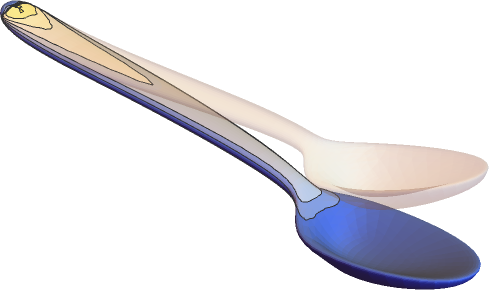
Compute the deflection of a spoon held fixed at the end and with a force applied at the top. Set up variables and parameters:
vars = {{u[x, y, z], v[x, y, z], w[x, y, z]}, {x, y, z}};
pars = <|"Material" -> ["Silver"]|>;Set up the PDE and the geometry:
spoon = \!\(\*Graphics3DBox[«8»]\);
displacement = NDSolveValue[{SolidMechanicsPDEComponent[vars, pars] == SolidBoundaryLoadValue[x >= 1 / 10, vars, pars, <|"Force" -> {0, 0, Quantity[-100, "Newtons"]}|>],
SolidFixedCondition[x <= -1 / 10, vars, pars]}, {u[x, y, z], v[x, y, z], w[x, y, z]}, {x, y, z}∈spoon];VectorDisplacementPlot3D[displacement, {x, y, z}∈spoon]Define a symbolic solid mechanics PDE model that considers thermal expansion:
SolidMechanicsPDEComponent[{{u[x, y, z], v[x, y, z], w[x, y, z]}, {x, y, z}}, <|"YoungModulus" -> , "PoissonRatio" -> , "ThermalExpansion" -> , "ThermalStrainTemperature" -> θ, "ThermalStrainReferenceTemperature" -> Subscript[θ, ref]|>]//MatrixFormCompute the deformation of a beam fixed to a wall under its own self-weight:
vars = {{u[x, y, z], v[x, y, z], w[x, y, z]}, {x, y, z}};
pars = <|"Material" -> Entity["Element", "Titanium"], "BodyLoadValue" -> {0, 0, -9.8}|>;
Ω = Cuboid[{0, 0, 0}, {1, 0.1, 0.1}];
gravityDisplacement = NDSolveValue[{SolidMechanicsPDEComponent[vars, Join[pars, <|
	"BodyLoadValue" -> {0, 0, -9.8}|>]] == {0, 0, 0}, SolidFixedCondition[x == 0, vars, pars]}, vars[[1]], {x, y, z}∈Ω];
Visualize an exaggeration of the deformed beam:
VectorDisplacementPlot3D[gravityDisplacement, {x, y, z}∈Ω]Stationary Plane Stress Analysis (4)
Compute the displacement of a rectangular steel plate held fixed at the left and with a forced displacement on the right. Set up the region, variables and parameters:
Ω = Rectangle[{0, 0}, {40 * 10 ^ -3, 30 * 10 ^ -3}];
vars = {{u[x, y], v[x, y]}, {x, y}};
pars = <|"SolidMechanicsModelForm" -> "PlaneStress", "YoungModulus" -> 200 * 10 ^ 9, "PoissonRatio" -> 0.3, "Thickness" -> 10 ^ -4|>;displacement = NDSolveValue[{SolidMechanicsPDEComponent[vars, pars] == {0, 0}, SolidFixedCondition[x == 0, vars, pars], SolidDisplacementCondition[x == 40 * 10 ^ -3, vars, pars, <|"Displacement" -> {-40 / 10 ^ 6, 0}|>]}, {u[x, y], v[x, y]}, {x, y}∈Ω]VectorDisplacementPlot[displacement, {x, y}∈Ω, Rule[...]]Compute a plane stress case as an extended model. This allows for the computation of the out-of-plane strain and verifies that the out-of-plane stress is 0. A rectangular steel plate is held fixed at the left and with a forced displacement on the right. Set up the region, variables and parameters. The variables now include all three directions:
Ω = Rectangle[{0, 0}, {40 * 10 ^ -3, 30 * 10 ^ -3}];
vars = {{u[x, y], v[x, y], w[x, y]}, {x, y, z}};
pars = <|"SolidMechanicsModelForm" -> "ExtendedPlaneStress", "YoungModulus" -> 200 * 10 ^ 9, "PoissonRatio" -> 0.3, "Thickness" -> 10 ^ -4|>;
Solve the equations with thee semi-dependent variables:
displacement = NDSolveValue[{SolidMechanicsPDEComponent[vars, pars] == {0, 0}, SolidDisplacementCondition[x == 0, vars, pars, <|"Displacement" -> {0, 0}|>], SolidDisplacementCondition[x == 40 * 10 ^ -3, vars, pars, <|"Displacement" -> {-40 / 10 ^ 6, 0}|>]}, {u[x, y], v[x, y], w[x, y]}, {x, y}∈Ω]Note that now there are three output variables in the list of displacements. Visualize the displacement for the main variables:
VectorDisplacementPlot[displacement[[1 ;; 2]], {x, y}∈Ω, Rule[...]]strain = SolidMechanicsStrain[vars, pars, displacement]Note, that the strain is a 3 by 3 array. Visualize the out-of-plane strain:
ContourPlot[strain[[3, 3]], {x, y}∈Ω, PlotRange -> All, PlotLegends -> Automatic]Compute the stress from the strain:
stress = SolidMechanicsStress[vars, pars, strain]Note, that the stress is a 3 by 3 array. Verify the plane stress condition:
stress[[3, 3]]Compute the displacement of a rectangular steel plate held fixed at the left and with a pressure applied at the right end. Set up the region, variables and parameters:
Ω = Rectangle[{0, 0}, {40 * 10 ^ -3, 30 * 10 ^ -3}];
vars = {{u[x, y], v[x, y]}, {x, y}};
pars = <|"SolidMechanicsModelForm" -> "PlaneStress", "YoungModulus" -> 200 * 10 ^ 9, "PoissonRatio" -> 0.3, "Thickness" -> 10 ^ -4|>;displacement = NDSolveValue[{SolidMechanicsPDEComponent[vars, pars] == SolidBoundaryLoadValue[x == 40 * 10 ^ -3, vars, pars, <|"Pressure" -> {3 10 ^ 4, 0}|>], SolidFixedCondition[x == 0, vars, pars]}, {u[x, y], v[x, y]}, {x, y}∈Ω]VectorDisplacementPlot[displacement, {x, y}∈Ω, Rule[...]]Compute the displacement of a rectangular steel plate held fixed at the bottom and with pressures applied at the remaining sides. Set up the region, variables and parameters:
Ω = Rectangle[{0, 0}, {1 / 25, 3 / 100}];
vars = {{u[x, y], v[x, y]}, {x, y}};
pars = <|"SolidMechanicsModelForm" -> "PlaneStress", "YoungModulus" -> 200 * 10 ^ 9, "PoissonRatio" -> 3 / 10, "Thickness" -> 10 ^ -4|>;displacement = NDSolveValue[{SolidMechanicsPDEComponent[vars, pars] == SolidBoundaryLoadValue[x == 1 / 25, vars, pars, <|"Pressure" -> {0, 2 * 10 ^ 8}|>] + SolidBoundaryLoadValue[y == 3 / 100, vars, pars, <|"Pressure" -> {2 * 10 ^ 8, 0}|>] +
SolidBoundaryLoadValue[x == 0, vars, pars, <|"Pressure" -> {0, -2 * 10 ^ 8}|>], SolidFixedCondition[y == 0, vars, pars]}, {u[x, y], v[x, y]}, {x, y}∈Ω]VectorDisplacementPlot[displacement, {x, y}∈Ω, Rule[...]]strain = SolidMechanicsStrain[vars, pars, displacement]Verify that the normal strain in the ![]() direction is about 0:
direction is about 0:
MinMax[strain[[1, 1]][[0]]["ValuesOnGrid"]]Visualize the normal strain in the ![]() direction:
direction:
VectorDisplacementPlot[{displacement, strain[[1, 1]]}, {x, y}∈Ω, Rule[...]]Verify that the normal strain in the ![]() direction is about 0:
direction is about 0:
MinMax[strain[[2, 2]][[0]]["ValuesOnGrid"]]Visualize the normal strain in the ![]() direction:
direction:
VectorDisplacementPlot[{displacement, strain[[2, 2]]}, {x, y}∈Ω, Rule[...]]MinMax[strain[[1, 2]][[0]]["ValuesOnGrid"]]Visualize the normal strain in the ![]() -
-![]() direction:
direction:
VectorDisplacementPlot[{displacement, strain[[1, 2]]}, {x, y}∈Ω, Rule[...]]Stationary Plane Strain Analysis (3)
Define a 2D plane strain PDE model:
SolidMechanicsPDEComponent[{{u[x, y], v[x, y]}, {x, y}}, <|"Material" -> Entity["Element", "Iron"], "SolidMechanicsModelForm" -> "PlaneStrain", "Thickness" -> 1|>]Define an extended plane strain PDE model:
SolidMechanicsPDEComponent[{{u[x, y], v[x, y], 0}, {x, y, z}}, <|"Material" -> Entity["Element", "Iron"], "SolidMechanicsModelForm" -> "ExtendedPlaneStrain", "Thickness" -> 1|>]Compute a plane strain case as an extended model. This allows for the computation of the out-of-plane stress and verifies that the out-of-plane strain is 0. Set up the region, variables and parameters. The variables now include all three directions:
Ω = Rectangle[];
pars = <|"SolidMechanicsModelForm" -> "ExtendedPlaneStrain", "YoungModulus" -> 30 * 10 ^ 3, "PoissonRatio" -> 3 / 10, "Thickness" -> 1|>;
vars = {{u[x, y], v[x, y], 0}, {x, y, z}};
Set up the solid mechanics PDE component:
op = SolidMechanicsPDEComponent[vars, pars]pde = {op == {0, 0}, SolidFixedCondition[x == 0, vars, pars], SolidDisplacementCondition[x == 1, vars, pars, <|"Displacement" -> {0.1, None}|>]};displacement = NDSolveValue[pde, {u[x, y], v[x, y], 0}, {x, y}∈Ω]Compute the strains from the displacements:
strain = SolidMechanicsStrain[vars, pars, displacement]Note that the strain is a 3×3 array. Verify the plane strain condition:
strain[[3, 3]]Compute the stress from the strain:
stress = SolidMechanicsStress[vars, pars, strain]Note that the stress is a 3×3 array. Visualize the out-of-plane stress:
ContourPlot[stress[[3, 3]], {x, y}∈Ω, PlotRange -> All, PlotLegends -> Automatic]Time-Dependent Analysis (3)
Define a time-dependent solid mechanics model for a particular material:
SolidMechanicsPDEComponent[{{u[t, x, y, z], v[t, x, y, z], w[t, x, y, z]}, t, {x, y, z}}, <|"Material" -> ["Silver"]|>]//MatrixFormSimulate a time-dependent force on a beam. Set up a region, variables and a material:
Ω = Cylinder[{{0, 0, 0}, {10, 0, 0}}, 1];
tvars = {{u[t, x, y, z], v[t, x, y, z], w[t, x, y, z]}, t, {x, y, z}};
pars = <|"Material" -> ["Iron"]|>;top = SolidMechanicsPDEComponent[tvars, pars];Create a time dependent force at the right end of the beam:
Subscript[Γ, load] = SolidBoundaryLoadValue[x == 10, tvars, pars, <|"Force" -> {0, 0, -Sin[2π t]500}|>];Subscript[Γ, wall] = SolidFixedCondition[x == 0, tvars, pars];Set up zero initial conditions and the initial velocity condition:
ics = {u[0, x, y, z] == 0, v[0, x, y, z] == 0, w[0, x, y, z] == 0, Derivative[1, 0, 0, 0][u][0, x, y, z] == 0, Derivative[1, 0, 0, 0][v][0, x, y, z] == 0, Derivative[1, 0, 0, 0][w][0, x, y, z] == 0};Solve the time-dependent PDE and monitor the progress:
tEnd = 5;
measure = AbsoluteTiming[
	Monitor[MaxMemoryUsed[
	transientDisplacement = NDSolveValue[{top == Subscript[Γ, load], Subscript[Γ, wall], ics}, {u[t, x, y, z], v[t, x, y, z], w[t, x, y, z]}, {x, y, z}∈Ω
	, {t, 0, tEnd}, MaxStepSize -> 0.05
	, EvaluationMonitor :> (monitor = Row[{"t = ", CForm[t]}])]] / 1024. ^ 2
	, monitor]];
Print["Time -> ", measure[[1]], "
Memory -> ", measure[[2]]]
Visualize the ![]() -displacement over time at a query point:
-displacement over time at a query point:
Plot[transientDisplacement[[3]] /. {x -> 10, y -> 0, z -> 0}, {t, 0, tEnd}]Simulate a time-dependent force on a cross section of a spoon considering a Rayleigh damping model. Set up a region, variables and a material:
vars = {{u[t, x, y], v[t, x, y]}, t, {x, y}};
pars = <|"Material" -> Entity["Element", "Copper"], "MassDamping" -> 40, "StiffnessDamping" -> 0.0004, "Thickness" -> 0.001, "SolidMechanicsModelForm" -> "PlaneStress"|>;
Set up the PDE and solve while monitoring progress:
AbsoluteTiming[Monitor[displacement = NDSolveValue[{SolidMechanicsPDEComponent[vars, pars] == SolidBoundaryLoadValue[x >= 1 / 10, vars, pars, <|"Force" -> {0, Quantity[-20, "Newtons"]}|>],
	SolidFixedCondition[x <= -1 / 10, vars, pars], {u[0, x, y] == 0, v[0, x, y] == 0, Derivative[1, 0, 0][u][0, x, y] == 0, Derivative[1, 0, 0][v][0, x, y] == 0}}, {u, v}, {x, y}∈[image], {t, 0, 0.05}
	, EvaluationMonitor :> (monitor = Row[{"t = ", CForm[t]}])]
	, monitor]]
Visualize the ![]() -displacement over time at a query point:
-displacement over time at a query point:
Plot[Evaluate[displacement[[2]][t, 0.17, 0.01]], {t, 0, 0.05}]frames = Table[VectorDisplacementPlot[Evaluate[Through[displacement[t, x, y]]], {x, y}∈[image], PlotRange -> {All, {-0.055, 0.045}}, VectorSizes -> Full],
{t, 0, 0.05, 0.0025}];
ListAnimate[frames, SaveDefinitions -> True]Eigenmode Analysis (2)
Define an eigenmode solid mechanics model for a particular material:
SolidMechanicsPDEComponent[{{u[t, x, y, z], v[t, x, y, z], w[t, x, y, z]}, t, {x, y, z}}, <|"Material" -> ["tungston"], "AnalysisType" -> "Eigenmode"|>]//MatrixFormCompute the eigenmodes of an iron bracket. Set up the region, variables and a material:
Ω = RegionDifference[Cuboid[{0, 0, 0}, {1, 1, 1}], Cuboid[{1 / 10, 1 / 10, 0}, {1, 9 / 10, 1}]];
tvars = {{u[t, x, y, z], v[t, x, y, z], w[t, x, y, z]}, t, {x, y, z}};
pars = <|"Material" -> ["Iron"], "AnalysisType" -> "Eigenmode"|>;Compute the eigenvalue and modes:
{evals, evecs} = NDEigensystem[{SolidMechanicsPDEComponent[tvars, pars] == {0, 0, 0}}, {u, v, w}, t, {x, y, z}∈Ω, 10];Visualize the seventh to tenth eigenmode:
mr = DiscretizeRegion[Ω];
Show[MeshRegion[5 * Table[Apply[if, m], {m, MeshCoordinates[mr]}, {if, #}] + MeshCoordinates[mr], MeshCells[mr, MeshCells[mr, {2, All}]]], Graphics3D[Style[mr, LightGray]]]& /@ evecs[[7 ;; 10]]
Hyperelastic Material Model (2)
Set up the variables and the model parameters for a piece of rubber that is held fixed at the left and a pressure is applied on the right. A neo-Hookean hyperelastic material model is used:
vars = {{u[x, y], v[x, y]}, {x, y}};
pars = <|"SolidMechanicsMaterialModel" -> "NeoHookean", "Thickness" -> 1, "ShearModulus" -> 5 10 ^ 8, "LameParameter" -> 10 ^ 9|>;Ω = RegionDifference[Rectangle[], Disk[{1 / 2, 1 / 2}, 1 / 4]];Set up the equation and solve for the displacement:
displacement = NDSolveValue[{SolidMechanicsPDEComponent[vars, pars] == SolidBoundaryLoadValue[x == 1, vars, pars, <|"Pressure" -> {9 * 10 ^ 8, 0}|>], SolidFixedCondition[x == 0, vars, pars]}, {u[x, y], v[x, y]}, {x, y}∈Ω];Visualize the deformed body over the original shape of the body:
VectorDisplacementPlot[displacement, {x, y}∈Ω, VectorSizes -> Full]Set up the variables and the model parameters for a neo-Hookean hyperelastic material model:
vars = {{u[x, y], v[x, y]}, {x, y}};
pars = <|"SolidMechanicsMaterialModel" -> "NeoHookean", "Compressibility" -> "Compressible", "LameParameter" -> 10 ^ 6, "ShearModulus" -> 5000, "SolidMechanicsModelForm" -> "PlaneStress", "Thickness" -> 0.01|>;
Create the PDE model with boundary conditions:
displacement2D = NDSolveValue[{SolidMechanicsPDEComponent[vars, pars] == SolidBoundaryLoadValue[x == 1, vars, pars, <|"Force" -> {Quantity[300, "Newtons"], 0}|>]
, SolidFixedCondition[x == 0, vars, pars]}, {u[x, y], v[x, y]}, {x, y}∈Rectangle[{0, 0}, {1, 1}]];VectorDisplacementPlot[displacement2D, {x, y}∈Rectangle[{0, 0}, {1, 1}], VectorSizes -> Full]strain = SolidMechanicsStrain[vars, pars, displacement2D]stress = SolidMechanicsStress[vars, pars, strain, displacement2D]Fiber Reinforced Material Model (1)
Set up the variables and the model parameters for a fiber-reinforced piece of rubber that is held fixed at the left and a pressure is applied on the right. A neo-Hookean hyperelastic material model is used:
vars = {{u[x, y], v[x, y]}, {x, y}};
pars = <|"ReinforcementDirectionVector" -> Normalize[{1, 1}], "SolidMechanicsMaterialModel" -> "NeoHookean", "Thickness" -> 1, "ShearModulus" -> 5 10 ^ 8, "LameParameter" -> 10 ^ 9|>;Ω = RegionDifference[Rectangle[], Disk[{1 / 2, 1 / 2}, 1 / 4]];Visualize the fiber reinforcement in the geometry:
StreamPlot[pars["ReinforcementDirectionVector"], {x, y}∈Ω, StreamMarkers -> "Segment", StreamColorFunction -> None, StreamStyle -> Black]Set up the equation and solve for the displacement:
displacement = NDSolveValue[{SolidMechanicsPDEComponent[vars, pars] == SolidBoundaryLoadValue[x == 1, vars, pars, <|"Pressure" -> {9 * 10 ^ 8, 0}|>], SolidFixedCondition[x == 0, vars, pars]}, {u[x, y], v[x, y]}, {x, y}∈Ω];Visualize the deformed body over the original shape of the body:
VectorDisplacementPlot[displacement, {x, y}∈Ω, VectorSizes -> Full]strain = SolidMechanicsStrain[vars, pars, displacement]stress = SolidMechanicsStress[vars, pars, strain, displacement]vms = VonMisesStress[vars, pars, stress]Visualize the von Mises stress:
VectorDisplacementPlot[{displacement, vms}, {x, y}∈Ω, VectorSizes -> Full]Multi-material Models (1)
A compliance matrix needs to be specified as a matrix. This is also true when a compliance matrix of a multi-material model is to be specified. This example shows how to do that. Specify two compliance matrices:
material1 = {{5.00, -1.55, -1.55, 0.00, 0.00, 0.00}, {-1.55, 5.00, -1.55, 0.00, 0.00, 0.00}, {-1.55, -1.55, 5.00, 0.00, 0.00, 0.00}, {0.00, 0.00, 0.00, 13.10, 0.00, 0.00}, {0.00, 0.00, 0.00, 0.00, 13.10, 0.00}, {0.00, 0.00, 0.00, 0.00, 0.00, 13.10}};
material2 = {{7.69, -2.62, -2.62, 0.00, 0.00, 0.00}, {-2.62, 7.69, -2.62, 0.00, 0.00, 0.00}, {-2.62, -2.62, 7.69, 0.00, 0.00, 0.00}, {0.00, 0.00, 0.00, 20.62, 0.00, 0.00}, {0.00, 0.00, 0.00, 0.00, 20.62, 0.00}, {0.00, 0.00, 0.00, 0.00, 0.00, 20.62}};
Create a multi-material compliance matrix, where material 1 is to be used for values in the geometry where ![]() , and material 2 is used in all other cases:
, and material 2 is used in all other cases:
complianceMatrix = MapThread[Piecewise[{{#1, y <= 0}}, #2]&, {material1, material2}, 2];Note that the compliance matrix now is a matrix:
MatrixQ[complianceMatrix]complianceMatrix[[2, 3]]Set up the parameters to make use of the multi-material compliance matrix:
pars = <|"MaterialModel" -> "LinearElastic", "MaterialSymmetry" -> "Anisotropic", "MassDensity" -> Piecewise[{{8960, y <= 0}}, 8908], "ComplianceMatrix" -> complianceMatrix|>;Create the solid mechanics PDE component:
SolidMechanicsPDEComponent[{{u[x, y, z], v[x, y, z], w[x, y, z]}, {x, y, z}}, pars]Non-axis-aligned Material Model (1)
For anisotropic elastic material that is not axis aligned, an orientation matrix can be specified to adjust the material to that. This also works with thermal expansion and is shown here. Variables and parameter are set up:
vars = {{u[x, y], v[x, y]}, {x, y}};
pars = <|"ModelForm" -> "PlaneStrain", "EngineeringStrain" -> False, "MaterialSymmetry" -> "Anisotropic", "OrientationMatrix" -> RotationMatrix[-ArcTan[x, y]], "ElasticityMatrix" -> {{(y (1 - ν)/(1 - 2 ν) (1 + ν)), (y ν/(1 - 2 ν) (1 + ν)), 0}, {(y ν/(1 - 2 ν) (1 + ν)), (y (1 - ν)/(1 - 2 ν) (1 + ν)), 0}, {0, 0, (y/2 (1 + ν))}} /. ν -> 1 / 3, "ThermalExpansion" -> {{0, 0}, {0, 1 / 10}},
	"ThermalStrainTemperature" -> 1,
"Thickness" -> 1|>;displacement = NDSolveValue[{SolidMechanicsPDEComponent[vars, pars] == {0, 0}, SolidDisplacementCondition[y == 0, vars, pars, <|"Displacement" -> {None, 0}|>], SolidFixedCondition[x == 1 && y == 0, vars, pars]}, {u[x, y], v[x, y]}, {x, y}∈Annulus[{0, 0}, {1, 2}, {0, π / 2}]];VectorDisplacementPlot[displacement, {x, y}∈Annulus[{0, 0}, {1, 2}, {0, π / 2}]]Applications (1)
Geotechnical (1)
When modeling soil in geotechnical applications, the Young modulus can change with the depth of the soil. This example explores a position-dependent Young's modulus. We use a rectangular slab of soild that is 100 meters wide and 100 meters deep:
Ω = Rectangle[{0, -100}, {100, 0}];
RegionPlot[Ω, PlotStyle -> Brown]
Next, we set up variables and parameters. At this point, we have a symbolic Young modulus ![]() :
:
vars = {{u[x, y], v[x, y]}, {x, y}};
pars = <|"YoungModulus" -> Y, "PoissonRatio" -> 1 / 3, "SolidMechanicsModelForm" -> "PlaneStrain", "Thickness" -> 100|>;op = SolidMechanicsPDEComponent[vars, pars];We have a force in the negative ![]() direction acting on part of the top:
direction acting on part of the top:
load = SolidBoundaryLoadValue[y == 0 && 25 <= x <= 75, vars, pars, <|"Force" -> {0, -10 ^ 8}|>];On the left- and right-hand side we constrain the movement in the ![]() direction; in the
direction; in the ![]() direction, the soil is able to move freely. At the bottom, the soil can move in the
direction, the soil is able to move freely. At the bottom, the soil can move in the ![]() direction but not in the
direction but not in the ![]() direction. This models a scenario where the soil is "standing" on a harder ground that does not move:
direction. This models a scenario where the soil is "standing" on a harder ground that does not move:
bcs = {SolidDisplacementCondition[x == 0 || x == 100, vars, pars, <|"Displacement" -> {0, None}|>], SolidDisplacementCondition[y == -100, vars, pars, <|"Displacement" -> {None, 0}|>]};baseYoungModulus = 50 * 10 ^ 6;Solve the PDE on a refined mesh with the Young modulus ![]() set to baseYoungModulus:
set to baseYoungModulus:
constantYDisplacement = NDSolveValue[{op == load, bcs} /. Y -> baseYoungModulus, {u[x, y], v[x, y]}, {x, y}∈Ω, Method -> {"PDEDiscretization" -> {"FiniteElement", "MeshOptions" -> {"MaxCellMeasure" -> 1}}}]VectorDisplacementPlot[constantYDisplacement, {x, y}∈Ω, PlotLegends -> Automatic]Create a helper function to compute the von Mises stress:
getVonMisesStress[vars_, pars_, displacement_] := Module[{strain, stress},
	strain = SolidMechanicsStrain[vars, pars, displacement];
	stress = SolidMechanicsStress[vars, pars, strain];
	VonMisesStress[vars, pars, stress]
	]
Compute the von Mises stress for the constant Young modulus:
constantYVonMisesStress = getVonMisesStress[vars, pars /. Y -> baseYoungModulus, constantYDisplacement]Make a contour plot of the von Mises stress:
ContourPlot[constantYVonMisesStress, {x, y}∈Ω, PlotLegends -> Automatic]Now we create a Young modulus depending on the depth ![]() :
:
variableYoungModulus = baseYoungModulus + 5 10 ^ 6RealAbs[y]ListLinePlot[Table[{variableYoungModulus, y}, {y, -100, 0}], GridLines -> Automatic, ImageSize -> Medium]Solve the PDE on a refined mesh with ![]() replaced with the variable-depth Young modulus:
replaced with the variable-depth Young modulus:
variableYDisplacement = NDSolveValue[{op == load, bcs} /. Y -> variableYoungModulus, {u[x, y], v[x, y]}, {x, y}∈Ω, Method -> {"PDEDiscretization" -> {"FiniteElement", "MeshOptions" -> {"MaxCellMeasure" -> 1}}}]VectorDisplacementPlot[variableYDisplacement, {x, y}∈Ω]variableYVonMisesStress = getVonMisesStress[vars, pars /. Y -> variableYoungModulus, variableYDisplacement]Visualize the von Mises stress:
ContourPlot[variableYVonMisesStress, {x, y}∈Ω, PlotLegends -> Automatic]Plot the difference between the von Mises stress of the two models:
ContourPlot[variableYVonMisesStress - constantYVonMisesStress, {x, y}∈Ω, PlotLegends -> Automatic]Plot the difference between the von Mises stress of the two models with the full plot range:
ContourPlot[variableYVonMisesStress - constantYVonMisesStress, {x, y}∈Ω, PlotLegends -> Automatic, PlotRange -> All]Text
Wolfram Research (2021), SolidMechanicsPDEComponent, Wolfram Language function, https://reference.wolfram.com/language/ref/SolidMechanicsPDEComponent.html (updated 2026).
CMS
Wolfram Language. 2021. "SolidMechanicsPDEComponent." Wolfram Language & System Documentation Center. Wolfram Research. Last Modified 2026. https://reference.wolfram.com/language/ref/SolidMechanicsPDEComponent.html.
APA
Wolfram Language. (2021). SolidMechanicsPDEComponent. Wolfram Language & System Documentation Center. Retrieved from https://reference.wolfram.com/language/ref/SolidMechanicsPDEComponent.html