

MeshRegion
MeshRegion[{p1,p2,…},{mcell1[{i1,…}],mcell2[{j1,…}],…}]
セル mcelljを持つメッシュを与える.ただし,整数 i として与えられる座標は piであるとみなされる.
MeshRegion[…,{…,wi[mcelli[…]],…}]
セルの特性が記号ラッパー wiで定義されたメッシュを与える.
MeshRegion[mreg,opts]
メッシュ領域 mreg からオプション opts のメッシュを与える.
詳細とオプション
- MeshRegionは,単体的複体あるいは胞複体としても知られている.
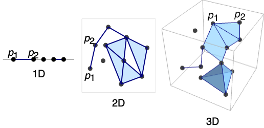
- MeshRegionは,次元1,2あるいは3に埋め込まれた任意の幾何次元の区分線形領域を表すことができる.
- MeshRegion[…]は,ノートブック中に,メッシュ領域のプロットとして表示される.
- MeshRegionは,一般に,DelaunayMesh,DiscretizeGraphics,DiscretizeRegion等の関数を使って作られる.
- MeshRegionで表される領域は,メッシュセルの非交和からなる.
- MeshRegionは,各点 piの長さと等しく,RegionEmbeddingDimensionを使って求めることができる,埋込み次元を持つ.
- 各セルは幾何次元を持ち,RegionDimensionを使って求めることができる.
- 可能なメッシュセル mcelliとその幾何次元
-
Point[i] 0 点 Line[{i1,i2,…}] 1 線分 {i1,i2}, {i2,i3}, … Triangle[{i1,i2,i3}] 2 塗り潰された三角形 Polygon[{i1,i2,…}] 2 塗り潰された多角形 Polyhedron[{{ii,i2,…},…}] 3 塗り潰された多面体 Tetrahedron[{i1,…,i4}] 3 塗り潰された四面体 Hexahedron[{i1,…,i8}] 3 塗り潰された六面体 Pyramid[{i1,…,i5}] 3 塗り潰された角錐 Prism[{i1,…,i6}] 3 塗り潰された角柱 Simplex[{i1,…,ik}] 0, 1, 2, 3 塗り潰されたシンプレックス - Tetrahedron,Hexahedron,Pyramid,およびPrismは,3D座標でのみ使うことができる.
- Point,Line,Triangle,Polygon,Polyhedron,Tetrahedron,Hexahedron,Pyramid,Prism,Simplexはどれも,複数のセル指定をも持っている.
- 次の特別ラッパー wiをセルに使うことができる.
-
Labeled[cell,…] cell にラベルを付けて表示する Style[cell,…] cell を指定のスタイルで示す Annotation[cell,namevalue] 注釈 name->value を cell に関連付ける - MeshRegion中の各セルは,{d,i}の形式の一意的なMeshCellIndexを与えられる.d は幾何次元,i は指標である.
- MeshRegionのセルを選ぶ目的のために,次のセル指定を使うことができる.
-
{d,i} 次元 d の指標 i のセル {d,ispec} 次元 d の指標指定 ispec のセル {dspec,…} dspec で与えられる次元のセル h[{i1,…}] 頭部 h,頂点指標 i1, …の明示的なセル {c1,c2,…} 明示的なセル ciのリスト - 指標指定 ispec は次の形でよい.
-
i セル指標 i {i1,i2,…} 指標 ikのセル All すべてのセル patt パターン patt にマッチする指標のセル - 次元指定 dspec は次の形でよい.
-
d 明示的な次元 d All 0から領域の幾何次元までのすべての次元 patt パターン patt にマッチする次元 - MeshRegionは,常に,最適化された表現に変換され,AtomQのような関数とパターンマッチの目的では生のものとして扱われる.
- MeshRegionには,埋込み次元2についてはGraphics,埋込み次元3についてはGraphics3Dのオプションと同じものに以下の追加・訂正を加えたものが使える.
-
MeshCellLabel Automatic セルのラベルと置き方 MeshCellShapeFunction Automatic セルの形状関数 MeshCellStyle Automatic セルのスタイル MeshCellHighlight {} ハイライトされたセルのリスト MeshCellMarker 0 セルの整数マーカー PlotTheme $PlotTheme メッシュの全体的なテーマ - PlotThemeの可能な設定には,共通の基本テーマ,フォントの特徴のテーマ,サイズの特徴のテーマがある.
- メッシュの特徴のテーマはメッシュセルのプロットに影響する.テーマには次のよのうなものがある.
-
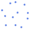
"Points" 0Dセル 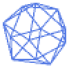
"Lines" 1Dセル,ワイヤーフレーム 
"Polygons" 2Dセル - 特徴のテーマの描画はメッシュの描画に影響する.テーマには次のよのうなものがある.
-

"SampledPoints" メッシュセルからサンプルされた点 
"SphereAndTube" 曲面としての点と円筒としての線 
"SmoothShading" 平滑化陰影付け 
"FaceNormals" 各2Dセルの法線 
"LargeMesh" 多数のセルについて最適化 - セルのスタイルその他の指定は,事実上,MeshCellStyle,Styleその他のラッパーの順に適用される.後の指定は先の指定を無効にする.
- セルラベルのスタイルその他の指定は,事実上,MeshCellLabel,Labeledの順に適用される.後の指定は先の指定を無効にする.
- MeshRegionはRegionMember,RegionDistance,RegionMeasure,NIntegrate等の関数で使うことができる.
例題
すべて開く すべて閉じる例 (6)
MeshRegion[{{0}, {1}, {2}, {3}}, {Line[{1, 2}], Line[{3, 4}]}]HighlightMesh[%, Labeled[0, "Index"]]MeshRegion[{{0, 0}, {1, 0}, {2, 1 / 2}, {2, -1 / 2}}, {Line[{1, 2}], Line[{2, 3}], Line[{3, 4}], Line[{4, 2}]}]HighlightMesh[%, Labeled[0, "Index"]]各点にその指標でラベルが付いた,3Dにおける2D(曲面)メッシュ領域:
ℛ = MeshRegion[{{0, 0, 0}, {0, 0, 1}, {0, -1, 0}, {1, 0, 0}, {0, 1, 0}}, {Triangle[{1, 2, 3}], Triangle[{1, 2, 4}], Triangle[{1, 2, 5}]}];HighlightMesh[ℛ, Labeled[0, "Index"]]各点にその指標でラベルが付いた,3Dにおける3D(立体)メッシュ領域:
ℛ = MeshRegion[{{0, 0, 0}, {2, 0, 0}, {2, 2, 0}, {0, 2, 0}, {1, 1, 2}}, {Tetrahedron[{1, 2, 3, 5}], Tetrahedron[{1, 3, 4, 5}]}];HighlightMesh[ℛ, Labeled[0, "Index"]]ℛ = MeshRegion[{{0, 0, 0}, {1, 0, 0}, {2, 0, 0}, {3, 0, -1 / 2}, {3, 0, 1 / 2}, {4, -1 / 2, 0}, {4, 1 / 2, 0}}, {Point[1], Line[{2, 3}], Triangle[{3, 4, 5}], Tetrahedron[{4, 6, 5, 7}]}];HighlightMesh[ℛ, Labeled[0, "Index"]]DelaunayMeshからの3Dの立体メッシュ領域:
DelaunayMesh[RandomReal[1, {50, 3}]]RegionMeasure[%]スコープ (41)
1D領域 (3)
厳密に0DのMeshRegionは点の集合である:
MeshRegion[{{0}, {1}, {2}}, Point[{{1}, {2}, {3}}]]点にHighlightMeshでラベルを付ける:
HighlightMesh[%, Labeled[0, "Index"]]厳密に1DのMeshRegionは線分の集合である:
MeshRegion[{{0}, {1}, {2}}, Line[{1, 2, 3}]]線分にHighlightMeshでラベルを付ける:
HighlightMesh[%, Labeled[1, "Index"]]MeshRegionは,次元が異なる要素を組み合せることができる:
MeshRegion[{{0}, {1}, {2}}, {Point[{1}], Line[{2, 3}]}]DimensionalMeshComponentsでそれぞれに分割する:
DimensionalMeshComponents[%]2D領域 (4)
厳密に0DのMeshRegionは点の集合である:
MeshRegion[Tuples[{0, 1, 2}, 2], Point[{List /@ Range[9]}]]点にHighlightMeshでラベルを付ける:
HighlightMesh[%, Labeled[0, "Index"]]厳密に1DのMeshRegionは線分の集合である:
MeshRegion[{{0, 0}, {1, 0}, {0, 1}, {1, 1}, {2, 1}}, Line[{{1, 2, 3, 1}, {4, 5}}]]線分にHighlightMeshでラベルを付ける:
HighlightMesh[%, Labeled[1, "Index"]]厳密に2DのMeshRegionは多角形の面の集合である:
MeshRegion[{{0, 0}, {1, 0}, {0, 1}, {1, 1}, {2, 1}, {2, 0}}, Polygon[{{1, 2, 3}, {4, 5, 6}}]]面にHighlightMeshでラベルを付ける:
HighlightMesh[%, Labeled[2, "Index"]]MeshRegionは,次元が異なる要素を組み合せることができる:
ℛ = MeshRegion[{{0, 0}, {1, 0}, {2, 0}, {3, -1 / 2}, {3, 1 / 2}}, {Point[{1}], Line[{2, 3}], Triangle[{3, 4, 5}]}]DimensionalMeshComponentsでそれぞれに分割する:
DimensionalMeshComponents[ℛ]3D領域 (5)
厳密に0DのMeshRegionは点の集合である:
MeshRegion[Tuples[{0, 1}, 3], Point[{List /@ Range[8]}]]点にHighlightMeshでラベルを付ける:
HighlightMesh[%, Labeled[0, "Index"]]厳密に1DのMeshRegionは線分の集合である:
MeshRegion[{{0, 0, 0}, {1, 0, 0}, {0, 1, 0}, {0, 0, 1}}, Line[Union[Sort /@ Permutations[Range[4], {2}]]]]線分にHighlightMeshでラベルを付ける:
HighlightMesh[%, Labeled[1, "Index"]]厳密に2DのMeshRegionは多角形の面の集合である:
MeshRegion[{{0, 0, 0}, {1, 0, 0}, {0, 1, 0}, {0, 0, 1}}, Polygon[{{1, 3, 2}, {4, 2, 3}, {3, 1, 4}}]]面にHighlightMeshでラベルを付ける:
HighlightMesh[%, Labeled[2, "Index"]]厳密に3DのMeshRegionは多面体立体の集合である:
MeshRegion[{{0, 0, 0}, {1, 0, 0}, {0, 1, 0}, {0, 0, 1}}, Tetrahedron[{1, 2, 3, 4}]]多面体立体のセルにはTetrahedron,Prism,Pyramid,Hexahedronが含まれる:
pts = {{0, 0, 0}, {1, 0, 0}, {1, 1, 0}, {0, 1, 0}, {0, 0, 1}, {1, 0, 1}, {1, 1, 1}, {0, 1, 1}, {0.5, 0.5, 1.5}, {1.5, 0, 0}, {1.5, 1, 0}, {1, -0.5, 0}};MeshRegion[pts, {Hexahedron[{1, 2, 3, 4, 5, 6, 7, 8}], Pyramid[{5, 6, 7, 8, 9}], Prism[{2, 10, 6, 3, 11, 7}], Tetrahedron[{2, 10, 6, 12}]}]MeshRegionは次元が異なる要素を組み合せることができる:
MeshRegion[{{0, 0, 0}, {1, 0, 0}, {2, 0, 0}, {3, 0, 1 / 2}, {3, 0, -1 / 2}, {4, 1 / 2, 0}, {4, -1 / 2, 0}}, {Simplex[{1}], Simplex[{2, 3}], Simplex[{3, 4, 5}], Simplex[{4, 5, 6, 7}]}]プレゼンテーション (11)
MeshCellLabelを使ってMeshRegionの一部にラベルを付けることができる:
MeshRegion[{{0, 0}, {1, 0}, {0, 1}}, Triangle[{1, 2, 3}], MeshCellLabel -> {0 -> "Index"}]MeshRegion[{{0, 0}, {1, 0}, {0, 1}}, Triangle[{1, 2, 3}], MeshCellLabel -> {{1, 1} -> Red, {1, 2} -> Green, {1, 3} -> Blue}]Labeledをラッパーとして使い,MeshRegionを構築するときにセルにラベルを付けることができる:
MeshRegion[{{0, 0}, {1, 0}, {1, 1}, {0, 1}}, {Labeled[Triangle[{1, 2, 3}], "a"], Labeled[Triangle[{3, 4, 1}], "b"]}]MeshRegion[{{0, 0}, {1, 0}, {1, 1}, {0, 1}}, {Labeled[Triangle[{1, 2, 3}], Sqrt[x ^ 2 + y ^ 2]], Labeled[Triangle[{3, 4, 1}], Red]}]MeshCellMarkerを使ってMeshRegionの一部に印を付けることができる:
MeshRegion[{{0, 0}, {1, 0}, {0, 1}}, Triangle[{1, 2, 3}], MeshCellMarker -> {{0, 1} -> 1, {0, 2} -> 2, {0, 3} -> 3}, MeshCellLabel -> {0 -> "Marker"}]MeshCellStyleを使ってMeshRegionの成分のStyleを設定することができる:
MeshRegion[{{0, 0}, {1, 0}, {0, 1}}, Triangle[{1, 2, 3}], MeshCellStyle -> {{1, 1} -> {Thick, StandardGray}, {1, 2} -> {Thick, Dashed, Green}, {1, 3} -> {Thickness[0.02], DotDashed, Blue}, {2, 1} -> LightRed}]Styleをラッパーとして使い,MeshRegionを構築する際にセルにスタイルを付けることができる:
MeshRegion[{{0, 0}, {1, 0}, {1, 1}, {0, 1}}, {Style[Polygon[{1, 2, 3}], Red], Style[Polygon[{3, 4, 1}], {Green, EdgeForm[Directive[Thick, StandardBlue]]}]}]MeshRegion[[image], PlotTheme -> "Points"]MeshRegion[[image], PlotTheme -> "Lines"]MeshRegion[[image], PlotTheme -> "Polygons"]MeshRegion[[image], PlotTheme -> "SampledPoints"]MeshRegion[[image], PlotTheme -> "SmoothShading"]MeshRegion[[image], PlotTheme -> "FaceNormals"]領域の特性 (8)
mr = DelaunayMesh[RandomReal[1, {20, 2}]];RegionEmbeddingDimension[mr]RegionDimension[mr]mr = DiscretizeRegion[Disk[]];{RegionMember[mr, {0, 0}], RegionMember[mr, {1, 1}]}mf = RegionMember[mr];
pts = RandomReal[{-1, 1}, {500, 2}];
Show[mr, Graphics[{Red, Point[Select[pts, mf]], StandardGray, Point[Select[pts, !mf[#]&]]}]]測度は1DメッシュではArcLength,2DメッシュではArea,3DメッシュではVolumeである:
{mr1, mr2, mr3} = DelaunayMesh[RandomReal[1, {20, #}]]& /@ Range[3]RegionDimension /@ {mr1, mr2, mr3}RegionMeasure /@ {mr1, mr2, mr3}{c1, c2, c3} = RegionCentroid /@ {mr1, mr2, mr3}{Show[mr1, Graphics[{Red, Point[Join[c1, {0}]]}]], Show[mr2, Graphics[{Red, Point[c2]}]], Show[HighlightMesh[mr3, Style[{2, All}, Opacity[0.2]]], Graphics3D[{Red, PointSize[Large], Point[c3]}]]}mr = DelaunayMesh[RandomReal[1, {10, 2}]];{RegionDistance[mr, {0.5, 0.5}], RegionDistance[mr, {2, 2}]}df = RegionDistance[mr];
{Plot3D[df[{x, y}], {x, -0.5, 1.5}, {y, -0.5, 1.5}, MeshFunctions -> {#3&}, Mesh -> 5], ContourPlot[df[{x, y}], {x, -1.5, 2.5}, {y, -1.5, 2.5}, Contours -> {{0.5, Red}, {1, Green}, {1.5, Blue}}]}mr = DelaunayMesh[RandomReal[1, {10, 2}]];{SignedRegionDistance[mr, {0.5, 0.5}], SignedRegionDistance[mr, {2, 2}]}sdf = SignedRegionDistance[mr];
Plot3D[sdf[{x, y}], {x, -0.5, 1.5}, {y, -0.5, 1.5}, MeshFunctions -> {#3&}, Mesh -> {{0}}, MeshShading -> {Red, Green}]mr = DelaunayMesh[RandomReal[1, {10, 2}]];{RegionNearest[mr, {0.5, 0.5}], RegionNearest[mr, {2, 2}]}pts = Table[{0.5, 0.5} + {Cos[k 2π / 16], Sin[k 2π / 16]}, {k, 0., 15}];
nst = RegionNearest[mr][pts];Legended[Show[mr, Graphics[{{Thin, Gray, Line[Transpose[{pts, nst}]]}, {Red, Point[pts]}, {Blue, Point[nst]}}]], PointLegend[{Red, Blue}, {"start", "nearest"}]]MeshRegionは常に有界である:
mr = DelaunayMesh[RandomReal[1, {20, 2}]];BoundedRegionQ[mr]rb = RegionBounds[mr]Show[Graphics[{EdgeForm[{Dashed, Red}], Opacity[0.1, Yellow], Cuboid@@Transpose[rb]}], mr]mr = MeshRegion[{{0, 0}, {1, 0}, {1, 1}, {0, 1}}, Polygon[{1, 2, 3, 4}]];Integrate[x y, {x, y}∈mr]メッシュ領域 (10)
MeshCellCountは,指定された次元あるいはセル指定にマッチするセルの数を返す:
mr = DelaunayMesh[RandomReal[1, {20, 2}]]MeshCellCount[mr, 1]MeshCellCount[mr]MeshCellsは,指定された次元あるいはセル指定にマッチしたメッシュ中のセルを返す:
mr = DelaunayMesh[RandomReal[1, {8, 2}]]MeshCells[mr, 1]MeshCells[mr, {{1, 1}, {2, 1}}]MeshCellIndexは,メッシュ中のセルあるいはセル集合の指標を得る:
mr = MeshRegion[{{0, 0}, {1, 0}, {0, 1}}, Polygon[{1, 2, 3}]]MeshCellIndex[mr, {Polygon[{1, 2, 3}], Line[{2, 3}], Point[{3}]}]MeshCoordinatesは,メッシュの座標を得る:
mr = DelaunayMesh[RandomReal[1, {8, 2}]]MeshCoordinates[mr]座標のリストはMeshCellsが参照するものである:
MeshCells[mr, {2, 1}]MeshPrimitivesは,メッシュを構成しているプリミティブを返す:
mr = DelaunayMesh[RandomReal[1, {8, 2}]]MeshPrimitives[mr, 0]MeshPrimitives[mr, {2, {1, 2, 3}}]DimensionalMeshComponentsは,メッシュ内の成分を次元ごとに分ける:
mr = MeshRegion[{{0, 0}, {1, 0}, {2, 0}, {3, -1 / 2}, {3, 1 / 2}}, {Point[{1}], Line[{2, 3}], Polygon[{3, 4, 5}]}]DimensionalMeshComponents[mr]ConnectedMeshComponentsは,連結性に基づいてメッシュの成分を分ける:
mr = DiscretizeRegion[RegionUnion[Disk[{0, 0}, 1], Disk[{3, 0}, 1]]]ConnectedMeshComponents[mr]MeshCellMeasureを使ってメッシュ中のセル集合の測度を得ることができる:
mr = DelaunayMesh[RandomReal[1, {20, 2}]]AnnotationValue[{mr, {2, {1, 2, 3, 4, 5}}}, MeshCellMeasure]AnnotationValue[{mr, {1, {8, 9, 10}}}, MeshCellMeasure]MeshCellCentroidを使って,メッシュ中のセル集合の重心を得ることができる:
mr = DelaunayMesh[RandomReal[1, {20, 2}]]c = AnnotationValue[{mr, {2, {1, 2, 3, 4, 5}}}, MeshCellCentroid]Show[mr, Graphics[{Red, Point[c]}]]MeshCellQualityを使ってメッシュ中のセル集合の品質を得ることができる:
mr = DelaunayMesh[RandomReal[1, {20, 2}]]AnnotationValue[{mr, 2}, MeshCellQuality]オプション (114)
AlignmentPoint (1)
 座標を使って3D Insetで整列する位置を指定する:
Table[Graphics[{Inset[MeshRegion[{{0, 0}, {2, -1}, {2, 1}}, {Triangle[{1, 2, 3}]}, ImageSize -> 50, AlignmentPoint -> {a, 0}], {0, 0}]}, ImageSize -> 100, Axes -> True, Ticks -> None], {a, {0, 1 / 2, 1}}]Table[Graphics[{Inset[MeshRegion[{{0, 0}, {2, -1}, {2, 1}}, {Triangle[{1, 2, 3}]}, ImageSize -> 50, AlignmentPoint -> {1 / 2, a}], {0, 0}]}, ImageSize -> 100, Axes -> True, Ticks -> None], {a, {0, 1 / 2, 1}}]AspectRatio (1)
AspectRatioに数値を使う:
Table[MeshRegion[{{0, 0}, {2, -1}, {2, 1}}, {Triangle[{1, 2, 3}]}, AspectRatio -> 1 / k], {k, 1, 3}]Axes (2)


AxesEdge (2)
MeshRegion[{{0, 0, 0}, {2, 0, 0}, {2, 2, 0}, {0, 2, 0}, {1, 1, 2}}, Pyramid[{1, 2, 3, 4, 5}], Boxed -> True, Axes -> True, AxesEdge -> Automatic]MeshRegion[{{0, 0, 0}, {2, 0, 0}, {2, 2, 0}, {0, 2, 0}, {1, 1, 2}}, Pyramid[{1, 2, 3, 4, 5}], Boxed -> True, Axes -> True, AxesEdge -> {{1, 1}, None, None}]AxesLabel (2)

AxesOrigin (2)
AxesStyle (2)
MeshRegion[{{0, 1}, {2, 0}, {2, 2}}, Triangle[{1, 2, 3}], Axes -> True, AxesStyle -> Directive[Orange, 12]]MeshRegion[{{0, 1}, {2, 0}, {2, 2}}, Triangle[{1, 2, 3}], Axes -> True, AxesStyle -> {Directive[Dashed, Red], Blue}]Background (1)
BaselinePosition (3)
{x, MeshRegion[{{0, 1}, {2, 0}, {2, 2}}, Triangle[{1, 2, 3}], ImageSize -> 50, BaselinePosition -> Center], y}Scaledを使い,グラフィックスのベースラインを高さの割合として指定する:
Table[{x, MeshRegion[{{0, 1}, {2, 0}, {2, 2}}, Triangle[{1, 2, 3}], ImageSize -> 50, BaselinePosition -> Scaled[b]]}, {b, {0, 0.5, 1}}]{x, MeshRegion[{{0, 1}, {2, 0}, {2, 2}}, Triangle[{1, 2, 3}], ImageSize -> 50, BaselinePosition -> Axis], y}BaseStyle (2)
Boxed (2)
BoxRatios (2)
MeshRegion[{{0, 0, 0}, {2, 0, 0}, {2, 2, 0}, {0, 2, 0}, {1, 1, 2}}, Pyramid[{1, 2, 3, 4, 5}], Boxed -> True, BoxRatios -> {1, 2, 3}]MeshRegion[{{0, 0, 0}, {2, 0, 0}, {2, 2, 0}, {0, 2, 0}, {1, 1, 2}}, Pyramid[{1, 2, 3, 4, 5}], Boxed -> True, Axes -> True, BoxRatios -> Automatic]BoxStyle (1)
Epilog (1)
FaceGrids (4)
MeshRegion[{{0, 0, 0}, {2, 0, 0}, {2, 2, 0}, {0, 2, 0}, {1, 1, 2}}, Pyramid[{1, 2, 3, 4, 5}], Axes -> True, Boxed -> True, FaceGrids -> All]

MeshRegion[{{0, 0, 0}, {2, 0, 0}, {2, 2, 0}, {0, 2, 0}, {1, 1, 2}}, Pyramid[{1, 2, 3, 4, 5}], Axes -> True, Boxed -> True, FaceGrids -> {{0, 0, 1}, {0, 0, -1}}]
MeshRegion[{{0, 0, 0}, {2, 0, 0}, {2, 2, 0}, {0, 2, 0}, {1, 1, 2}}, Pyramid[{1, 2, 3, 4, 5}], Axes -> True, Boxed -> True, FaceGrids -> {{0, -1, 0}}]


MeshRegion[{{0, 0, 0}, {2, 0, 0}, {2, 2, 0}, {0, 2, 0}, {1, 1, 2}}, Pyramid[{1, 2, 3, 4, 5}], Axes -> True, Boxed -> True, FaceGrids -> {{{0, -1, 0}, {{1}, {2 / 3, 4 / 3}}}}]FaceGridsStyle (1)
Frame (2)
FrameLabel (2)
FrameStyle (2)
MeshRegion[{{0, 1}, {2, 0}, {2, 2}}, Triangle[{1, 2, 3}], Frame -> True, FrameStyle -> Directive[Thick, Gray]]MeshRegion[{{0, 1}, {2, 0}, {2, 2}}, Triangle[{1, 2, 3}], Frame -> True, FrameStyle -> {{Thick, Directive[Thick, Dashed]}, {Blue, Red}}]FrameTicks (3)
MeshRegion[{{0, 1}, {2, 0}, {2, 2}}, Triangle[{1, 2, 3}], Frame -> True, FrameTicks -> None]MeshRegion[{{0, 1}, {2, 0}, {2, 2}}, Triangle[{1, 2, 3}], Frame -> True, FrameTicks -> Automatic]MeshRegion[{{0, 1}, {2, 0}, {2, 2}}, Triangle[{1, 2, 3}], Frame -> True, FrameTicks -> {{None, Automatic}, {Automatic, None}}]FrameTicksStyle (2)
MeshRegion[{{0, 1}, {2, 0}, {2, 2}}, Triangle[{1, 2, 3}], Frame -> True, FrameTicksStyle -> Directive[Orange, 12]]MeshRegion[{{0, 1}, {2, 0}, {2, 2}}, Triangle[{1, 2, 3}], Frame -> True, FrameTicksStyle -> {{Green, Blue}, {Red, Green}}]GridLines (3)
MeshRegion[{{0, 1}, {2, 0}, {2, 2}}, Triangle[{1, 2, 3}], GridLines -> Automatic]MeshRegion[{{0, 1}, {2, 0}, {2, 2}}, Triangle[{1, 2, 3}], Axes -> True, GridLines -> {{.5, 1.5}, {.5, 1.5}}]MeshRegion[{{-1, 0}, {1, -1}, {1, 1}}, Triangle[{1, 2, 3}], Axes -> True, GridLines -> {{{-1, Orange}, {-.5, Dotted}, {.5, Dotted}, {1, Orange}}, {-1, {-.5, Dotted}, {.5, Dotted}, 1}}]GridLinesStyle (1)
ImageMargins (3)
ImageSizeの外側に余白を置かない:
Framed[MeshRegion[{{0, 1}, {2, 0}, {2, 2}}, Triangle[{1, 2, 3}]]]Framed[MeshRegion[{{0, 1}, {2, 0}, {2, 2}}, Triangle[{1, 2, 3}], ImageMargins -> 20]]Framed[MeshRegion[{{0, 1}, {2, 0}, {2, 2}}, Triangle[{1, 2, 3}], ImageMargins -> {{5, 10}, {20, 30}}]]ImagePadding (4)
MeshRegion[{{0, 1}, {2, 0}, {2, 2}}, Triangle[{1, 2, 3}], ImagePadding -> None, Frame -> True, FrameLabel -> {x, y}]Framed[MeshRegion[{{0, 1}, {2, 0}, {2, 2}}, Triangle[{1, 2, 3}], ImagePadding -> All, Frame -> True, FrameLabel -> {x, y}], FrameMargins -> 0]Framed[MeshRegion[{{0, 1}, {2, 0}, {2, 2}}, Triangle[{1, 2, 3}], ImagePadding -> 40, Frame -> True]]Framed[MeshRegion[{{0, 1}, {2, 0}, {2, 2}}, Triangle[{1, 2, 3}], ImagePadding -> {{40, 10}, {20, 5}}, Frame -> True]]ImageSize (3)
Table[MeshRegion[{{0, 1}, {2, 0}, {2, 2}}, Triangle[{1, 2, 3}], ImageSize -> s], {s, {Tiny, Small}}]{MeshRegion[{{0, 1}, {2, 0}, {2, 2}}, Triangle[{1, 2, 3}], ImageSize -> 100], MeshRegion[{{0, 2}, {2, 0}, {2, 4}}, Triangle[{1, 2, 3}], ImageSize -> 100]}{MeshRegion[{{0, 1}, {2, 0}, {2, 2}}, Triangle[{1, 2, 3}], ImageSize -> {100, 100}], MeshRegion[{{0, 2}, {2, 0}, {2, 4}}, Triangle[{1, 2, 3}], ImageSize -> {100, 100}]}LabelStyle (1)
Lighting (4)
MeshRegion[{{0, 0, 0}, {2, 0, 0}, {2, 2, 0}, {0, 2, 0}, {1, 1, 2}}, Pyramid[{1, 2, 3, 4, 5}], Lighting -> {{"Ambient", Orange}}]Table[MeshRegion[{{0, 0, 0}, {2, 0, 0}, {2, 2, 0}, {0, 2, 0}, {1, 1, 2}}, Pyramid[{1, 2, 3, 4, 5}], Lighting -> {{"Directional", c, {{1.5, 0, 2}, {0, 0, 0}}}}], {c, {Red, Yellow, Blue}}]Table[MeshRegion[{{0, 0, 0}, {2, 0, 0}, {2, 2, 0}, {0, 2, 0}, {1, 1, 2}}, Pyramid[{1, 2, 3, 4, 5}], Lighting -> {{"Point", c, {1.5, 0, 3}}}], {c, {Red, Yellow, Blue}}]Table[MeshRegion[{{0, 0, 0}, {2, 0, 0}, {2, 2, 0}, {0, 2, 0}, {1, 1, 2}}, Pyramid[{1, 2, 3, 4, 5}], Lighting -> {{"Spot", c, {{1, 1, 2.5}, {1, 1, 2}}, Pi / 8}}], {c, {Red, Yellow, Blue}}]MeshCellHighlight (3)
MeshCellHighlightでは,MeshRegionの部分的なハイライトを指定することができる:
MeshRegion[{{0, 0}, {1, 0}, {2, 1 / 2}, {2, -1 / 2}}, {Line[{1, 2}], Line[{2, 3}], Line[{3, 4}], Line[{4, 2}]},
	MeshCellHighlight -> {{1, All} -> Red, {0, All} -> Green}]
面を透過的にすることで3D MeshRegionの内部構造を見ることができる:
MeshRegion[{{0, 0, 0}, {2, 0, 0}, {2, 2, 0}, {0, 2, 0}, {1, 1, 2}}, {Tetrahedron[{1, 2, 3, 5}], Tetrahedron[{1, 3, 4, 5}]}, MeshCellHighlight -> {{2, All} -> Opacity[0.5, Orange]}]MeshRegion[{{0}, {1}, {2}}, Line[{{1, 2, 3}}], MeshCellHighlight -> {{1, 1} -> {Thick, Red}, {1, 2} -> {Dashed, Green}}]MeshRegion[{{0}, {1}, {2}}, Line[{{1, 2, 3}}], MeshCellHighlight -> {Line[{1, 2}] -> {Thick, Red}, Line[{2, 3}] -> {Dashed, Green}}]MeshCellLabel (3)
MeshCellLabelを使ってMeshRegionの各部分にラベルを付けることができる:
MeshRegion[{{0}, {1}, {2}}, Point[{{1}, {2}, {3}}], MeshCellLabel -> {0 -> "Index"}]MeshRegion[{{0, 0}, {1, 0}, {1, 1}, {0, 1}}, Polygon[{1, 2, 3, 4}], MeshCellLabel -> {0 -> "Index", 1 -> "Index"}]MeshRegion[{{0}, {1}, {2}}, Line[{{1, 2, 3}}], MeshCellLabel -> {{1, 1} -> "x", {1, 2} -> "y"}]MeshRegion[{{0}, {1}, {2}}, Line[{{1, 2, 3}}], MeshCellLabel -> {Line[{1, 2}] -> "x", Line[{2, 3}] -> "y"}]MeshCellMarker (1)
MeshCellMarkerを使ってMeshRegionの部分に値を割り当てることができる:
MeshRegion[{{0}, {1}, {2}}, Point[{{1}, {2}, {3}}], MeshCellMarker -> {{0, 1} -> 1, {0, 2} -> 2, {0, 3} -> 3}]MeshCellLabelを使ってマーカーを示す:
MeshRegion[{{0}, {1}, {2}}, Point[{{1}, {2}, {3}}], MeshCellMarker -> {{0, 1} -> 1, {0, 2} -> 2, {0, 3} -> 3}, MeshCellLabel -> {0 -> "Marker"}]MeshCellShapeFunction (2)
MeshCellShapeFunctionは,MeshRegionの部分についての関数を指定することができる:
MeshRegion[{{0, 0}, {1, 0}, {2, 1 / 2}, {2, -1 / 2}}, {Line[{1, 2}], Line[{2, 3}], Line[{3, 4}], Line[{4, 2}]},
MeshCellShapeFunction -> {1 -> (Arrow[#]&), 0 -> (Disk[#, .1]&)}]MeshRegion[{{0, 0}, {1, 0}, {2, 1 / 2}, {2, -1 / 2}}, {Line[{1, 2}], Line[{2, 3}], Line[{3, 4}], Line[{4, 2}]},
MeshCellShapeFunction -> {{0, 1} -> (Disk[#, .1]&), {0, 2} -> (Disk[#, {.1, .05}]&)}]MeshRegion[{{0, 0}, {1, 0}, {2, 1 / 2}, {2, -1 / 2}}, {Line[{1, 2}], Line[{2, 3}], Line[{3, 4}], Line[{4, 2}]},
MeshCellShapeFunction -> {Point[1] -> (Disk[#, .1]&), Point[2] -> (Disk[#, {.1, .05}]&)}]MeshCellStyle (3)
MeshCellStyleを使うと,MeshRegionの部分のスタイルを指定することができる:
MeshRegion[{{0, 0}, {1, 0}, {2, 1 / 2}, {2, -1 / 2}}, {Line[{1, 2}], Line[{2, 3}], Line[{3, 4}], Line[{4, 2}]},
MeshCellStyle -> {{1, All} -> Red, {0, All} -> Green}]面を透過的にすることで,3DMeshRegionの内部構造が見えるようになる:
MeshRegion[{{0, 0, 0}, {2, 0, 0}, {2, 2, 0}, {0, 2, 0}, {1, 1, 2}}, {Tetrahedron[{1, 2, 3, 5}], Tetrahedron[{1, 3, 4, 5}]}, MeshCellStyle -> {{2, All} -> Opacity[0.5, Orange]}]個々のセルに,それ自身のセル指標を使ってスタイル付けすることができる:
MeshRegion[{{0}, {1}, {2}}, Line[{{1, 2, 3}}], MeshCellStyle -> {{1, 1} -> {Thick, Red}, {1, 2} -> {Dashed, Green}}]MeshRegion[{{0}, {1}, {2}}, Line[{{1, 2, 3}}], MeshCellStyle -> {Line[{1, 2}] -> {Thick, Red}, Line[{2, 3}] -> {Dashed, Green}}]PlotLabel (2)
TraditionalForm中のグラフィックスの上にラベルを表示する:
MeshRegion[{{0, 1}, {2, 0}, {2, 2}}, Triangle[{1, 2, 3}], PlotLabel -> x ^ 2 + y ^ 2 == 1]Styleおよび他のタイプセット関数を使ってラベルの見え方を変更する:
MeshRegion[{{-1, 0}, {1, -1}, {1, 1}}, Triangle[{1, 2, 3}], PlotLabel -> Style[Framed[x ^ 2 + y ^ 2 == 1], 16, Red, Background -> Yellow]]PlotRange (3)
MeshRegion[{{0, 1}, {2, 0}, {2, 2}}, Triangle[{1, 2, 3}], Frame -> True, PlotRange -> All]

MeshRegion[{{-1, 0}, {1, -1}, {1, 1}}, Triangle[{1, 2, 3}], PlotRange -> {{-1, 1}, {0, 1}}, Frame -> True]PlotRangeでの切取りを強制する:
MeshRegion[{{-1, 0}, {1, -1}, {1, 1}}, Triangle[{1, 2, 3}], PlotRange -> {{-1, 1}, {0, 1}}, PlotRangeClipping -> True, Frame -> True]PlotRange -> s はPlotRange -> {{-s, s}, {-s, s}}に等しい:
MeshRegion[{{-2, 0}, {2, -2}, {2, 2}}, Triangle[{1, 2, 3}], Frame -> True, PlotRange -> 1]PlotRangeClipping (2)
グラフィックスオブジェクトがPlotRangeを超えて広がることを許す:
MeshRegion[{{-2, 0}, {2, -2}, {2, 2}}, Triangle[{1, 2, 3}], Frame -> True, PlotRange -> 1, PlotRangeClipping -> False]PlotRangeですべてのグラフィックスオブジェクトを切り取る:
MeshRegion[{{-2, 0}, {2, -2}, {2, 2}}, Triangle[{1, 2, 3}], Frame -> True, PlotRange -> 1, PlotRangeClipping -> True]PlotRangePadding (3)
MeshRegion[{{0, 1}, {2, 0}, {2, 2}}, Triangle[{1, 2, 3}], PlotRangePadding -> 1, Frame -> True]Scaled座標を使って充填を含む:
MeshRegion[{{0, 1}, {2, 0}, {2, 2}}, Triangle[{1, 2, 3}], PlotRangePadding -> Scaled[0.1], Frame -> True]MeshRegion[{{0, 1}, {2, 0}, {2, 2}}, Triangle[{1, 2, 3}], PlotRangePadding -> {{0.5, 1}, {0.3, 0.3}}, Frame -> True]PlotRegion (3)
MeshRegion[{{0, 1}, {2, 0}, {2, 2}}, Triangle[{1, 2, 3}], Frame -> True, FrameTicks -> False, Background -> StandardBlue]グラフィックスのコンテンツを各方向に領域の真ん中半分に制限する:
MeshRegion[{{0, 1}, {2, 0}, {2, 2}}, Triangle[{1, 2, 3}], Frame -> True, FrameTicks -> False, PlotRegion -> {{0.25, 0.75}, {0.25, 0.75}}, Background -> StandardBlue]ImagePaddingを使ってグラフィックスの周りに充填を加えることもできる:
MeshRegion[{{0, 1}, {2, 0}, {2, 2}}, Triangle[{1, 2, 3}], Frame -> True, FrameTicks -> False, ImagePadding -> 30, Background -> StandardBlue]PlotTheme (9)
基本テーマ (2)
MeshRegion[{{0, 0, 0}, {2, 0, 0}, {2, 2, 0}, {0, 2, 0}, {1, 1, 2}}, Pyramid[{1, 2, 3, 4, 5}], PlotTheme -> "Detailed"]MeshRegion[{{0, 0, 0}, {2, 0, 0}, {2, 2, 0}, {0, 2, 0}, {1, 1, 2}}, Pyramid[{1, 2, 3, 4, 5}], PlotTheme -> "Monochrome"]特徴テーマ (7)
MeshRegion[{{0, 0, 0}, {2, 0, 0}, {2, 2, 0}, {0, 2, 0}, {1, 1, 2}}, Pyramid[{1, 2, 3, 4, 5}], PlotTheme -> "Points"]MeshRegion[{{0, 0, 0}, {2, 0, 0}, {2, 2, 0}, {0, 2, 0}, {1, 1, 2}}, Pyramid[{1, 2, 3, 4, 5}], PlotTheme -> "Lines"]MeshRegion[{{0, 0, 0}, {2, 0, 0}, {2, 2, 0}, {0, 2, 0}, {1, 1, 2}}, Pyramid[{1, 2, 3, 4, 5}], PlotTheme -> "Polygons"]MeshRegion[{{0, 0, 0}, {2, 0, 0}, {2, 2, 0}, {0, 2, 0}, {1, 1, 2}}, Pyramid[{1, 2, 3, 4, 5}], PlotTheme -> "SampledPoints"]MeshRegion[{{0, 0, 0}, {2, 0, 0}, {2, 2, 0}, {0, 2, 0}, {1, 1, 2}}, Pyramid[{1, 2, 3, 4, 5}], PlotTheme -> "SphereAndTube"]MeshRegion[{{0, 0, 0}, {2, 0, 0}, {2, 2, 0}, {0, 2, 0}, {1, 1, 2}}, Pyramid[{1, 2, 3, 4, 5}], PlotTheme -> "SmoothShading"]MeshRegion[{{0, 0, 0}, {2, 0, 0}, {2, 2, 0}, {0, 2, 0}, {1, 1, 2}}, Pyramid[{1, 2, 3, 4, 5}], PlotTheme -> "FaceNormals"]Prolog (1)
bg = Graphics[Polygon[{{0, 0}, {1, 0}, {1, 1}, {0, 1}}, VertexColors -> {Orange, Orange, White, White}], AspectRatio -> Full];MeshRegion[{{0, 1}, {2, 0}, {2, 2}}, Triangle[{1, 2, 3}], Prolog -> Inset[bg, Scaled[{0, 0}], Scaled[{0, 0}]]]MeshRegion[{{0, 0}, {1, 0}, {2, 1 / 2}, {2, -1 / 2}}, {Line[{1, 2}], Line[{2, 3}], Line[{3, 4}], Line[{4, 2}]}, Prolog -> Inset[bg, Scaled[{0, 0}], Scaled[{0, 0}]]]RotateLabel (2)
MeshRegion[{{0, 1}, {2, 0}, {2, 2}}, Triangle[{1, 2, 3}], Frame -> True, FrameLabel -> {None, "y axis"}, RotateLabel -> True]MeshRegion[{{0, 1}, {2, 0}, {2, 2}}, Triangle[{1, 2, 3}], Frame -> True, FrameLabel -> {None, "y axis"}, RotateLabel -> False]SphericalRegion (2)
連続する画像が,向きとは無関係に,一貫した大きさになるようにする:
Table[MeshRegion[{{0, 0, 0}, {2, 0, 0}, {2, 2, 0}, {0, 2, 0}, {1, 1, 2}}, Pyramid[{1, 2, 3, 4, 5}], SphericalRegion -> True, ImageSize -> 80, ViewPoint -> 3.{ Sin[t], Cos[t], 1}], {t, 0, 4}]SphericalRegionがないと,各画像は可能な限り大きくなる:
Table[MeshRegion[{{0, 0, 0}, {2, 0, 0}, {2, 2, 0}, {0, 2, 0}, {1, 1, 2}}, Pyramid[{1, 2, 3, 4, 5}], ImageSize -> 80, ViewPoint -> 3.{ Sin[t], Cos[t], 1}], {t, 0, 4}]Ticks (3)
MeshRegion[{{0, 1}, {2, 0}, {2, 2}}, Triangle[{1, 2, 3}], Axes -> True, Ticks -> None]MeshRegion[{{0, 1}, {2, 0}, {2, 2}}, Triangle[{1, 2, 3}], Axes -> True, Ticks -> Automatic]MeshRegion[{{0, 1}, {2, 0}, {2, 2}}, Triangle[{1, 2, 3}], Ticks -> {{1, 2, 3}, {1, 3}}, Axes -> True]TicksStyle (2)
MeshRegion[{{0, 1}, {2, 0}, {2, 2}}, Triangle[{1, 2, 3}], Axes -> True, TicksStyle -> Directive[Red, Bold]]

MeshRegion[{{0, 1}, {2, 0}, {2, 2}}, Triangle[{1, 2, 3}], Axes -> True, TicksStyle -> {Directive[Red, Bold], Directive[Blue, 12]}]ViewAngle (1)
ViewCenter (1)
ViewMatrix (1)

ViewPoint (3)
MeshRegion[{{0, 0, 0}, {2, 0, 0}, {2, 2, 0}, {0, 2, 0}, {1, 1, 2}}, Pyramid[{1, 2, 3, 4, 5}], ViewPoint -> {Pi, Pi / 2, 2}]{MeshRegion[{{0, 0, 0}, {2, 0, 0}, {2, 2, 0}, {0, 2, 0}, {1, 1, 2}}, Pyramid[{1, 2, 3, 4, 5}], ViewPoint -> Front],
MeshRegion[{{0, 0, 0}, {2, 0, 0}, {2, 2, 0}, {0, 2, 0}, {1, 1, 2}}, Pyramid[{1, 2, 3, 4, 5}], ViewPoint -> Top]}{MeshRegion[{{0, 0, 0}, {2, 0, 0}, {2, 2, 0}, {0, 2, 0}, {1, 1, 2}}, Pyramid[{1, 2, 3, 4, 5}], ViewPoint -> {0, -Infinity, 0}],
MeshRegion[{{0, 0, 0}, {2, 0, 0}, {2, 2, 0}, {0, 2, 0}, {1, 1, 2}}, Pyramid[{1, 2, 3, 4, 5}], ViewPoint -> {0, 0, Infinity}]}ViewRange (2)
デフォルトで,範囲はすべてのオブジェクトを含むのに十分になっている:
MeshRegion[{{0, 0, 0}, {2, 0, 0}, {2, 2, 0}, {0, 2, 0}, {1, 1, 2}}, Pyramid[{1, 2, 3, 4, 5}], ViewPoint -> {1, 0, 1.5}, SphericalRegion -> True]MeshRegion[{{0, 0, 0}, {2, 0, 0}, {2, 2, 0}, {0, 2, 0}, {1, 1, 2}}, Pyramid[{1, 2, 3, 4, 5}], ViewPoint -> {1, 0, 1.5}, ViewRange -> {3.5, 7.2}, SphericalRegion -> True]ViewVector (1)
ViewVertical (2)

MeshRegion[{{0, 0, 0}, {2, 0, 0}, {2, 2, 0}, {0, 2, 0}, {1, 1, 2}}, Pyramid[{1, 2, 3, 4, 5}], ViewVertical -> {1, 0, 0}]Table[MeshRegion[{{0, 0, 0}, {2, 0, 0}, {2, 2, 0}, {0, 2, 0}, {1, 1, 2}}, Pyramid[{1, 2, 3, 4, 5}], ViewVertical -> v], {v, {{1, 0, 1}, {.5, 0, 1}, {0, -.5, 1}, {0, -1, 1}}}]アプリケーション (9)
曲線 (4)
MeshRegionから線を抽出し,ワイヤーフレームメッシュを作る:
ℛ = VoronoiMesh[RandomReal[1, {50, 2}]]MeshCellsで与えられる指標は,MeshCoordinatesに対応する:
{pts, lines} = {MeshCoordinates[ℛ], MeshCells[ℛ, 1]};wireframe = MeshRegion[pts, lines]RegionDimension /@ {ℛ, wireframe}Area /@ {ℛ, wireframe}ArcLength /@ {ℛ, wireframe}RegularLineMesh[n_Integer] :=
MeshRegion[Table[{Cos[k 2π / n], Sin[k 2π / n]}, {k, n}], Line[Append[Range[n], 1]]]rl = Table[RegularLineMesh[n], {n, 3, 10}]ArcLength /@ rl
Table[ArcLength[RegularLineMesh[n]], {n, {10, 10 ^ 2, 10 ^ 3}}]L(Lindenmayer)システムを使ってコッホ(Koch)曲線のメッシュ領域を作る:
ProductionString[n_] := Characters@Nest[StringReplace[#, {"F" -> "F-F+F+F-F"}]&, "F", n - 1];タートルグラフィックスを使って,座標に対する出力文字列内の文字を解釈するための関数を定義する:
Turtle[pts_, d_]["+"] := Turtle[pts, RotateRight[d]]Turtle[pts_, d_]["-"] := Turtle[pts, RotateLeft[d]]Turtle[{pp___, pt_}, d : {dxdy_, ___}]["F"] := Turtle[{pp, pt, pt + dxdy}, d]start = {0, 0};
dirs = {{1, 0}, {0, 1}, {-1, 0}, {0, -1}};pts = Table[First@Fold[#1[#2]&, Turtle[{start}, dirs], ProductionString[n]], {n, 4}];curves = Table[MeshRegion[p, Line[Range@Length@p]], {p, pts}]
ArcLength /@ curvesFindSequenceFunction[Rationalize[%], n]グラフをMeshRegionに変換する:
GraphMesh[g_ ? GraphQ] :=
MeshRegion[GraphEmbedding[g], Line[{##}]&@@@EdgeList[UndirectedGraph[g]]]GraphMesh /@ {StarGraph[7], WheelGraph[7], CycleGraph[7], GridGraph[{5, 5}], CompleteKaryTree[4]}ArcLength /@ %GraphMesh /@ Graph3D /@ {StarGraph[11], CycleGraph[7], GridGraph[{5, 5, 5}], CompleteKaryTree[4]}ArcLength /@ %NIntegrate[x^2y^2z^2, {x, y, z}∈[image]]曲面 (3)
GraphSurfaceMesh[g_ ? GraphQ] :=
RegionProduct[MeshRegion[GraphEmbedding[g], Line[{##}]&@@@EdgeList[UndirectedGraph[g]]], MeshRegion[{{0}, {1}}, Line[{1, 2}]]]GraphSurfaceMesh /@ {StarGraph[7], WheelGraph[7], CycleGraph[7], GridGraph[{5, 5}], CompleteKaryTree[4]}結果の領域を使って計算することができる.この場合は曲面積分が計算できる:
NIntegrate[x^2y^2z^2, {x, y, z}∈[image]]長方形の格子メッシュを直接生成する.ここではFlattenがするように,IndexFlattenが位置指標を平坦化する:
IndexFlatten[i_List, d_List] := 1 + FoldList[Times, 1, Most[Reverse[d]]].Reverse[(i - 1)]GridMesh[{{l1_, l2_}, {u1_, u2_}}, {k1_, k2_}] :=
Module[{pa, ia, re},
pa = Table[{x, y}, {x, l1, u1, (u1 - l1) / k1}, {y, l2, u2, (u2 - l2) / k2}];
re = {{1, 1}, {2, 1}, {2, 2}, {1, 2}};
ia = Table[IndexFlatten[#, {k1, k2} + 1]& /@ TranslationTransform[{dx, dy}][re], {dx, 0, k1 - 1}, {dy, 0, k2 - 1}];
MeshRegion[Flatten[pa, 1], Polygon[Flatten[ia, 1]]]
]GridMesh[{{0, 0}, {1, 1}}, {3, 3}]1Dメッシュの積として同じメッシュ領域を生成することもできる:
mr1d = MeshRegion[{{0}, {1 / 3}, {2 / 3}, {1}}, Line[{1, 2, 3, 4}]]RegionProduct[mr1d, mr1d]上記の直接法を一般化し,パターン行列に対応するメッシュ領域を生成する:
IndexFlatten[i_List, d_List] := 1 + FoldList[Times, 1, Most[Reverse[d]]].Reverse[(i - 1)]PatternGridMesh[a_List] /; MatrixQ[a] :=
Module[{m, n, pa, ia, re},
{m, n} = Dimensions[a];
pa = Table[{x, y}, {x, 0, m}, {y, 0, n}];
re = {{1, 1}, {2, 1}, {2, 2}, {1, 2}};
ia = Table[IndexFlatten[#, {m, n} + 1]& /@ TranslationTransform[ind - 1][re], {ind, Position[a, 1]}];
MeshRegion[Flatten[pa, 1], Polygon[ia]]
]PatternGridMesh[{{1, 0}, {0, 1}}]PatternGridMesh[Table[If[Mod[i, 4] == 2 && Mod[j, 4] == 2, 0, 1], {i, 11}, {j, 11}]]PatternGridMesh[CellularAutomaton[30, {{1}, 0}, 50]]立体 (2)
長方形格子メッシュを直接生成する.ここでは,Flattenがするのと同じように,IndexFlattenが位置指標を平坦化する:
IndexFlatten[i_List, d_List] := 1 + FoldList[Times, 1, Most[Reverse[d]]].Reverse[(i - 1)]GridMesh[{{l1_, l2_, l3_}, {u1_, u2_, u3_}}, {k1_, k2_, k3_}] :=
Module[{pa, ia, re},
pa = Table[{x, y, z}, {x, l1, u1, (u1 - l1) / k1}, {y, l2, u2, (u2 - l2) / k2}, {z, l3, u3, (u3 - l3) / k3}];
re = {{1, 1, 1}, {2, 1, 1}, {2, 2, 1}, {1, 2, 1}, {1, 1, 2}, {2, 1, 2}, {2, 2, 2}, {1, 2, 2}};
ia = Table[IndexFlatten[#, {k1, k2, k3} + 1]& /@ TranslationTransform[{dx, dy, dz}][re], {dx, 0, k1 - 1}, {dy, 0, k2 - 1}, {dz, 0, k3 - 1}];
MeshRegion[Flatten[pa, 2], Hexahedron[Flatten[ia, 2]]]
]GridMesh[{{0, 0, 0}, {1, 1, 1}}, {3, 3, 3}]同じメッシュ領域を1Dメッシュの積として生成することもできる:
mr1d = MeshRegion[{{0}, {1 / 3}, {2 / 3}, {1}}, Line[{1, 2, 3, 4}]]RegionProduct[mr1d, mr1d, mr1d]上記の直接法を一般化して,パターン行列に対応するメッシュ領域を生成する:
IndexFlatten[i_List, d_List] := 1 + FoldList[Times, 1, Most[Reverse[d]]].Reverse[(i - 1)]PatternGridMesh[a_List] /; ArrayQ[a] && ArrayDepth[a] == 3 :=
Module[{m, n, p, pa, ia, re},
{m, n, p} = Dimensions[a];
pa = Table[{x, y, z}, {x, 0, m}, {y, 0, n}, {z, 0, p}];
re = {{1, 1, 1}, {2, 1, 1}, {2, 2, 1}, {1, 2, 1}, {1, 1, 2}, {2, 1, 2}, {2, 2, 2}, {1, 2, 2}};
ia = Table[IndexFlatten[#, {m, n, p} + 1]& /@ TranslationTransform[ind - 1][re], {ind, Position[a, 1]}];
MeshRegion[Flatten[pa, 2], Hexahedron[ia]]
]PatternGridMesh[{{{1, 1, 1}, {1, 0, 1}, {1, 1, 1}},
{{1, 1, 1}, {1, 0, 1}, {1, 1, 1}}, {{1, 1, 1}, {1, 0, 1}, {1, 1, 1}}}]PatternGridMesh[CellularAutomaton[{14, {2, 1}, {1, 1}}, {{{1}}, 0}, 10]]上記の考え方を使ってSeidelメッシュ,つまり,あらゆる方向にトンネルが通っていてしかも交差しないメッシュ領域を構築する:
SeidelMesh[{r_, s_, t_}] :=
PatternGridMesh[Table[If[Mod[i, 4] == 2 && Mod[j, 4] == 2 || Mod[i, 4] == 0 && Mod[k, 4] == 0 || Mod[j, 4] == 0 && Mod[k, 4] == 2, 0, 1], {i, 3 + r 4}, {j, 3 + s 4}, {k, 3 + t 4}]]SeidelMesh[{1, 1, 1}]境界メッシュに変換しスタイルを施すことで,理解が簡単になる:
HighlightMesh[BoundaryMesh@SeidelMesh[{2, 2, 2}], {Style[1, None], Style[2, Opacity[0.5]]}]HighlightMesh[BoundaryMesh@SeidelMesh[{4, 4, 4}], {Style[1, None], Style[2, Opacity[0.5]]}]特性と関係 (9)
MeshRegionは任意の幾何次元を持つことができる:
point = MeshRegion[{{0, 0}}, {Point[1]}];
line = MeshRegion[{{0, 0}, {1, 1}}, {Line[{1, 2}]}];
polygon = MeshRegion[{{0, 0}, {1, 0}, {1, 1}}, {Polygon[{1, 2, 3}]}];
polytope = MeshRegion[{{0, 0, 0}, {1, 0, 0}, {0, 1, 0}, {0, 0, 1}}, {Tetrahedron[{1, 2, 3, 4}]}];RegionDimension /@ {point, line, polygon, polytope}MeshRegionは常に有界である:
ℛ = MeshRegion[{{0, 0}, {1, 0}, {0, 1}}, Polygon[{1, 2, 3}]];BoundedRegionQを使って調べ,RegionBoundsを使って実際の境界を調べる:
{BoundedRegionQ[ℛ], rr = RegionBounds[ℛ]}Show[ℛ, Graphics[{EdgeForm[Directive[Dashed, Red]], Yellow, Opacity[0.1], Cuboid@@Transpose[rr]}]]MeshRegionQを使って領域がMeshRegionかどうかを調べることができる:
ℛ = MeshRegion[{{0, 0}, {1, 0}, {0, 1}}, Polygon[{1, 2, 3}]]MeshRegionQ[ℛ]DelaunayMeshを使って点の集合からMeshRegionを作る:
{p2, p3} = RandomReal[1, {20, #}]& /@ {2, 3};DelaunayMesh /@ {p2, p3}TriangulateMeshを使ってBoundaryMeshRegionをMeshRegionに変換する:
ℛ = BoundaryMeshRegion[{{0, 0}, {1, 0}, {1, 1}}, Line[{1, 2, 3, 1}]]TriangulateMesh[ℛ]DiscretizeRegionを使って任意の領域をMeshRegionに変換する:
DiscretizeRegion[ImplicitRegion[x ^ 2 + y ^ 2 ≤ 1, {x, y}]]DiscretizeGraphicsを使ってGraphicsをMeshRegionに変換する:
g = Graphics[{Orange, Disk[{2, 2}], Brown, Rectangle[{0, 0}, {2, 2}], Line[{{0, 0}, {4, 0}}]}]DiscretizeGraphics[g]MeshRegionQ[%]Showを使って任意のMeshRegionをGraphicsに変換する:
ℛ = MeshRegion[{{0, 0}, {1, 0}, {0, 1}}, Polygon[{1, 2, 3}]]Show[ℛ]//InputFormMeshRegionは,BoundaryMeshRegionよりメモリを多く必要とすることが多い:
pts = RandomReal[1, {50, 2}];
ℛ1 = DelaunayMesh[pts];
ℛ2 = BoundaryMesh[ℛ1];{ℛ1, ℛ2}ByteCount /@ {ℛ1, ℛ2}テキスト
Wolfram Research (2014), MeshRegion, Wolfram言語関数, https://reference.wolfram.com/language/ref/MeshRegion.html (2022年に更新).
CMS
Wolfram Language. 2014. "MeshRegion." Wolfram Language & System Documentation Center. Wolfram Research. Last Modified 2022. https://reference.wolfram.com/language/ref/MeshRegion.html.
APA
Wolfram Language. (2014). MeshRegion. Wolfram Language & System Documentation Center. Retrieved from https://reference.wolfram.com/language/ref/MeshRegion.html