-
See Also
- Show
- Plot3D
- ListPlot3D
- ParametricPlot3D
- RegionPlot3D
- ContourPlot3D
- ListContourPlot3D
- Graphics
- DiscretizeGraphics
- BoundaryDiscretizeGraphics
- Printout3D
-
- Formats
- PLY
- STL
- X3D
-
- Front End Tokens
- Import
- Related Guides
- Workflows
- Tech Notes
Graphics3D[primitives,options]
represents a three-dimensional graphical image.


Graphics3D
Graphics3D[primitives,options]
represents a three-dimensional graphical image.
Details and Options
- Graphics3D is displayed in StandardForm as a graphical image. In InputForm, it is displayed as an explicit list of primitives.
- The following graphics primitives can be used:
-
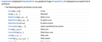
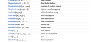
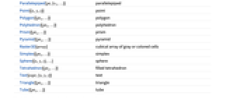
Arrow[{pt1,pt2}] arrow Ball[{x,y,z},…] filled ball BezierCurve[{pt1,pt2,…}] Bézier curve BSplineCurve[{pt1,pt2,…}] B-spline curve BSplineSurface[array] B-spline surface Circumsphere[{pt1,…}] sphere specified by four points Cone[{pt1,pt2},r] filled cone ConicHullRegion[…] filled linear cone Cube[{x,y,z},…] filled cube Cuboid[{xmin,ymin,zmin},…] filled cuboid Cylinder[{{x1,x2,x3},…},…] filled cylinder Dodecahedron[{x,y,z},…] filled dodecahedron GraphicsComplex[pts,prims] complex of graphics objects GraphicsGroup[{g1,g2,…}] objects treated as a group HalfLine[{pt1,pt2}] half-infinite line, or ray HalfPlane[{pt1,pt2},v] half-infinite plane Hexahedron[{pt1,…}] filled hexahedron Icosahedron[{x,y,z},…] filled icosahedron InfiniteLine[{pt1,pt2}] infinite line InfinitePlane[{pt1,pt2,pt2}] infinite plane Inset[obj,…] inset object JoinedCurve[{seg1,seg2,…}] joined curve segments Line[{pt1,…}] line Octahedron[{x,y,z},…] filled octahedron Parallelepiped[pt,{v1,…}] parallelepiped Point[{x,y,z}] point Polygon[{pt1,…}] polygon Polyhedron[{pt1,…}] polyhedron Prism[{pt1,…}] prism Pyramid[{pt1,…}] pyramid Raster3D[array] cubical array of gray or colored cells Simplex[{pt1,…}] simplex Sphere[{x,y,z},…] sphere Tetrahedron[{pt1,…}] filled tetrahedron Text[expr,{x,y,z}] text Triangle[{pt1,…}] triangle Tube[{pt1,…}] tube - The following graphics directives can be used:
-
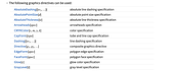
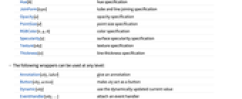
AbsoluteDashing[{w1,…}] absolute line dashing specification AbsolutePointSize[d] absolute point size specification AbsoluteThickness[w] absolute line thickness specification Arrowheads[spec] arrowheads specification CMYKColor[c,m,y,k] color specification CapForm[type] tube and line cap specification Dashing[{w1,…}] line dashing specification Directive[g1,g2,…] composite graphics directive EdgeForm[spec] polygon edge specification FaceForm[spec] polygon face specification Glow[c] glow color specification GrayLevel[i] gray‐level specification Hue[h] hue specification JoinForm[type] tube and line joining specification Opacity[a] opacity specification PointSize[d] point size specification RGBColor[r,g,b] color specification Specularity[s] surface specularity specification Texture[obj] texture specification Thickness[w] line thickness specification - The following wrappers can be used at any level:
-
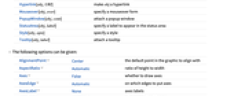
Annotation[obj,label] give an annotation Button[obj,action] make obj act as a button Dynamic[obj] use the dynamically updated current value EventHandler[obj,…] attach an event handler Hyperlink[obj,URI] make obj a hyperlink Mouseover[obj,over] specify a mouseover form PopupWindow[obj,cont] attach a popup window StatusArea[obj,label] specify a label to appear in the status area Style[obj,opts] specify a style Tooltip[obj,label] attach a tooltip - The following options can be given:
-
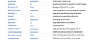
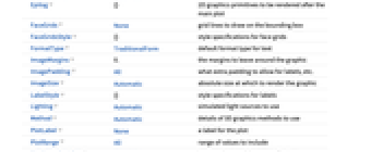
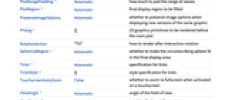
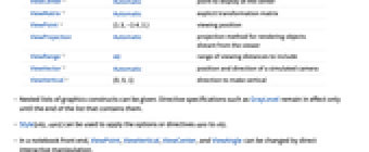
AlignmentPoint Center the default point in the graphic to align with AspectRatio Automatic ratio of height to width Axes False whether to draw axes AxesEdge Automatic on which edges to put axes AxesLabel None axes labels AxesOrigin Automatic where axes should cross AxesStyle {} graphics directives to specify the style for axes Background None background color for the plot BaselinePosition Automatic how to align with a surrounding text baseline BaseStyle {} base style specifications for the graphic Boxed True whether to draw the bounding box BoxRatios Automatic bounding 3D box ratios BoxStyle {} style specifications for the box ClipPlanes None clipping planes ClipPlanesStyle Automatic style specifications for clipping planes ContentSelectable Automatic whether to allow contents to be selected ControllerLinking False when to link to external rotation controllers ControllerPath Automatic what external controllers to try to use Epilog {} 2D graphics primitives to be rendered after the main plot FaceGrids None grid lines to draw on the bounding box FaceGridsStyle {} style specifications for face grids FormatType TraditionalForm default format type for text ImageMargins 0. the margins to leave around the graphic ImagePadding All what extra padding to allow for labels, etc. ImageSize Automatic absolute size at which to render the graphic LabelStyle {} style specifications for labels Lighting Automatic simulated light sources to use Method Automatic details of 3D graphics methods to use PlotLabel None a label for the plot PlotRange All range of values to include PlotRangePadding Automatic how much to pad the range of values PlotRegion Automatic final display region to be filled PreserveImageOptions Automatic whether to preserve image options when displaying new versions of the same graphic Prolog {} 2D graphics primitives to be rendered before the main plot RotationAction "Fit" how to render after interactive rotation SphericalRegion Automatic whether to make the circumscribing sphere fit in the final display area Ticks Automatic specification for ticks TicksStyle {} style specification for ticks TouchscreenAutoZoom False whether to zoom to fullscreen when activated on a touchscreen ViewAngle Automatic angle of the field of view ViewCenter Automatic point to display at the center ViewMatrix Automatic explicit transformation matrix ViewPoint {1.3,-2.4,2.} viewing position ViewProjection Automatic projection method for rendering objects distant from the viewer ViewRange All range of viewing distances to include ViewVector Automatic position and direction of a simulated camera ViewVertical {0,0,1} direction to make vertical - Nested lists of graphics constructs can be given. Directive specifications such as GrayLevel remain in effect only until the end of the list that contains them.
- Style[obj,opts] can be used to apply the options or directives opts to obj.
- In a notebook front end, ViewPoint, ViewVertical, ViewCenter, and ViewAngle can be changed by direct interactive manipulation.
- Dragging with the mouse rotates a 3D graphic.
- Directives such as RGBColor specify surface colors for objects that follow. Final colors are determined from simulated illumination, including Glow and Specularity components.
- By default, four light sources of different colors are used, arranged at particular fixed locations outside the bounding box.
- By default, ViewAngle is set so that, if possible, the projection of the whole 3D object just fills the 2D viewing area.
- The settings for BaseStyle are appended to the default style typically given by the "Graphics3D" style in the current stylesheet. The settings for BoxStyle, LabelStyle, etc. are appended to the default styles given for "Graphics3DBox", "Graphics3DLabel", etc.
- Settings that can be given through the Method option include "SpherePoints", "CylinderPoints", "RotationControl", and "ShrinkWrap". »
- The following options can be given to Method:
-
"AxesDuringInteraction" "Lock" axes layout/display when rotating "ConePoints" {40,3} how many subdivisions to model Cone with "CylinderPoints" {40,3} how many subdivisions to model Cylinder with "EdgeDepthOffset" True draw edges above faces at similar depths "InvertSurfaceNormals" False invert the normals of a BSplineSurface "PerFragmentLighting" True shade faces interpolating between VertexNormals "RelieveDPZFighting" False reduce the effects of Z-fighting "RotationControl" "ArcBall" set the rotation controller "RotationMode" "ClippedRegion" specify the rotation mode "ShrinkWrap" False crop out empty space around rendered content "SpherePoints" {40,30} how many subdivisions to model Sphere with "SplinePoints" {7,7} how many subdivisions to model BSplineSurface with "TubePoints" Automatic how many subdivisions to model Tube with - Graphics3D[] gives an empty 3D graphic.
Examples
open all close allBasic Examples (3)
Use lines, polygons, cylinders, spheres, etc. to build up a 3D graphics scene:
Use plot functions to automatically create Graphics3D from different types of data:
Scope (14)
Primitives (2)
Three-dimensional planar polygons can fold over themselves:
Vertices can be shared by using GraphicsComplex:
Directives (5)
Directives can specify color, opacity, and specularity of faces:
Specify the specular exponent:
Colors, thickness, and dashing directives affect lines and edges:
Specify different properties for front and back of faces:
Graphics directives normally remain in effect only until the end of the list that contains them:
Coordinates (2)
Options (86)
AlignmentPoint (1)
Specify the position to be aligned in 3D Inset, using ![]() coordinates:
coordinates:
AxesEdge (3)
AxesStyle (1)
BaselinePosition (2)
Align the center of a graphic with the baseline of the text:
Specify the baseline of a graphic as a fraction of the height by using Scaled:
BoxRatios (2)
FaceGrids (4)
FormatType (2)
By default, expressions are displayed using TraditionalForm in graphics:
Display expressions using StandardForm:
ImagePadding (4)
Thick lines and labels outside of the bounding box can be clipped without ImagePadding:
Leave enough padding for labels:
ImageSize (3)
Lighting (4)
Method (14)
"AxesDuringInteraction" (1)
"EdgeDepthOffset" (1)
"EdgeDepthOffset"->True ensures that edges placed near faces are not obscured:
"InvertSurfaceNormals" (1)
Invert the direction of the surface normals of a BSplineSurface:
"OneLayer" (1)
"PerFragmentLighting" (1)
"RelieveDPZFighting" (1)
By default, z-fighting of coplanar polygons is typically resolved by the rendering system:
"RelieveDPZFighting"->False improves rendering performance at the cost of exposing z-fighting:
"RotationMode" (1)
Normally, a 3D graphic in rotation changes its apparent size to accommodate its ImageSize:
"SphericalRegion" resizes the graphic to accommodate all orientations during rotation:
"ShrinkWrap" (1)
"SplinePoints" (1)
PlotLabel (2)
Display a label on the top of the graphic in TraditionalForm:
Use Style and other typesetting functions to modify how the label appears:
PlotRange (3)
PlotRangePadding (3)
PlotRegion (3)
The contents of a graphic use the whole region:
Limit the contents of the graphic to the middle half of the region in each direction:
ImagePadding can also be used to add padding around a graphic:
SphericalRegion (1)
Make a sequence of images be consistently sized, independent of orientation:
Without SphericalRegion, each image is made as big as possible:
TicksStyle (2)
ViewCenter (2)
Place the top-right corner of the object at the center of the final image:
Use the ViewCenter->{vc,vp} to specify that 3D point vc gets mapped to the 2D point vp:
ViewPoint (3)
ViewRange (2)
Properties & Relations (5)
The StandardForm of Graphics3D is its rendered form:
The InputForm is the textual expression form:
Graphics3D can be used as input to functions:
Three-dimensional plot functions return Graphics3D:
Several integrated data sources return Graphics3D:
Many Import and Export formats support Graphics3D:
See Also
Show Plot3D ListPlot3D ParametricPlot3D RegionPlot3D ContourPlot3D ListContourPlot3D Graphics DiscretizeGraphics BoundaryDiscretizeGraphics Printout3D
Front End Tokens: Import
Function Repository: Stereogram3D
Tech Notes
Related Guides
Related Workflows
- Make a 3D Printout ▪
- Control Interactive Content with a Gamepad
History
Introduced in 1988 (1.0) | Updated in 1996 (3.0) ▪ 2007 (6.0) ▪ 2008 (7.0) ▪ 2010 (8.0) ▪ 2012 (9.0) ▪ 2014 (10.0) ▪ 2017 (11.2) ▪ 2019 (12.0) ▪ 2020 (12.1) ▪ 2024 (14.0)
Text
Wolfram Research (1988), Graphics3D, Wolfram Language function, https://reference.wolfram.com/language/ref/Graphics3D.html (updated 2024).
CMS
Wolfram Language. 1988. "Graphics3D." Wolfram Language & System Documentation Center. Wolfram Research. Last Modified 2024. https://reference.wolfram.com/language/ref/Graphics3D.html.
APA
Wolfram Language. (1988). Graphics3D. Wolfram Language & System Documentation Center. Retrieved from https://reference.wolfram.com/language/ref/Graphics3D.html
BibTeX
@misc{reference.wolfram_2025_graphics3d, author="Wolfram Research", title="{Graphics3D}", year="2024", howpublished="\url{https://reference.wolfram.com/language/ref/Graphics3D.html}", note=[Accessed: 28-December-2025]}
BibLaTeX
@online{reference.wolfram_2025_graphics3d, organization={Wolfram Research}, title={Graphics3D}, year={2024}, url={https://reference.wolfram.com/language/ref/Graphics3D.html}, note=[Accessed: 28-December-2025]}